Percipio Viewer is an image viewing software developed by Percipio.XYZ based on the Percipio Camport SDK. It can provide real-time preview of the camera’s output, including depth images, color images, infrared images, and point clouds.
Percipio Viewer is available in both Windows and Linux versions, and it is recommended to use the Windows version. The following sections will use the Percipio Viewer (Windows version) as an example to introduce its interface and functions.
Complete the following steps before using Percipio Viewer:
Download the .zip file from Download Section on Percipio official website and unzip it to obtain the percipio-viewer-X.X.X.exe file.
Connect the Percipio camera to the host computer and power it.
Method I
Connect the camera directly to the computer’s gigabit Ethernet interface via a gigabit Ethernet cable.
Power the camera by an external power supply via the power cable Percipio provides. For detailed descriptions on the power connector, see the specifications for each camera model.
Method II
Connect the camera and the computer to the same Gigabit Ethernet PoE via Gigabit Ethernet cables.
With this method, PoE also serves as a power supply for the camera. If the camera you obtain does not support POE power supply, please power it by an external power supply.
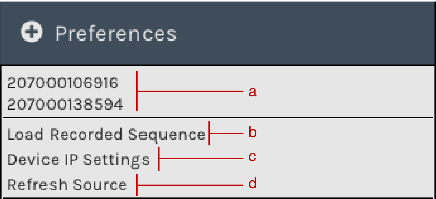
In Net interface list column, select the network interface of the target network segment or choose All network interfaces.
In Found device column, select the target camera’s serial number (SN).
Fill in Device mac address, Device target IP, Device target gate, and Device target mask.
Note
If the Device target IP field is left blank, the camera’s IP address will be set to a dynamic one. If filled in, it will be set to a static IP address.
Click on Accept.
The message “Device IP setting is successful” in the log display area indicates that the IP has been successfully set.
The message “Device IP setting failed” in the log display area indicates that the IP setting has failed. Check your computer’s network configuration and hardware connections, and ensure that the parameters on the Device IP Settings page are filled in correctly.
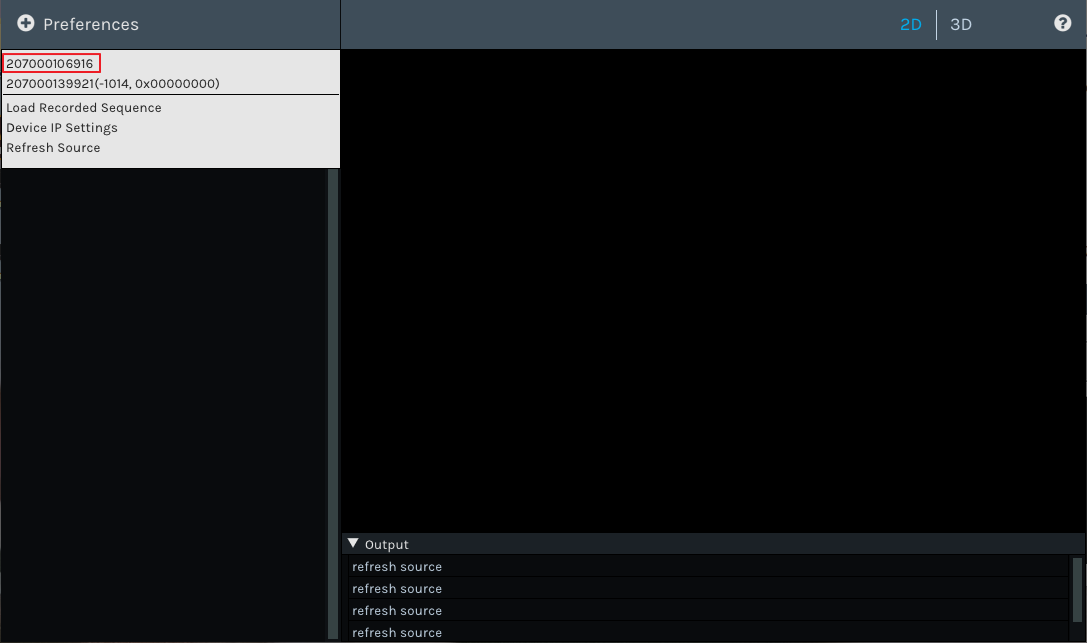
If the camera status code and firmware error code are displayed after the serial number in the device list (as shown in the above image -1014, 0x00000000), it indicates that the camera cannot be opened normally. Please check the camera status code in the image below. If the camera status code is -1024, it is necessary to determine the abnormal condition based on the firmware error code.
Percipio Viewer supports setting the work mode of the camera, and the camera captures images according to the settings.
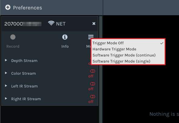
Click on when all data streams are in status , and select the work mode according to the table below.
Work Mode
Camera Operating Status
Trigger Mode Off
After the data stream is toggled on, the camera captures images continuously at the highest frame rate.
Hardware Trigger Mode
An external hardware trigger signal source needs to be connected to the camera. Then after toggling on the data stream, the camera captures images according to the frequency of the trigger signal .
Software Trigger Mode (continue)
After the data stream is toggled on, the camera captures images upon receiving a software trigger signal.
Software Trigger Mode (single)
With data streams toggled on, the camera captures one frame of image upon clicking on the button.
The selected work mode will have an icon √ displayed on its right side.
Percipio Viewer supports previewing depth images, color images, left/right infrared images, point clouds, and adjusting component parameters.
To preview images, do the following:
Toggle on the data stream to preview the corresponding image in real-time in the image display area.
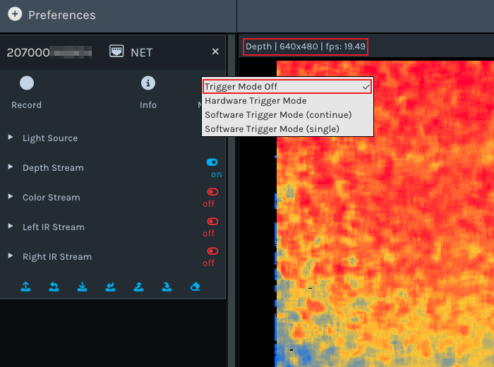
The title bar above the image displays the current data stream name, image resolution, and frame rate.
Depth Image, Color Image, and Left/Right Infrared Image
Expand the page by clicking on on the left side of the data stream, and adjust parameters according to actual needs.
Note
Some parameters can only be modified when the data stream is in status . It is recommended to refer to the logs in the log display area for instructions.
Different camera models support different parameters, and the display on the Percipio Viewer interface changes accordingly. The following table describes the parameters (taking the PS800-E1 camera as an example).
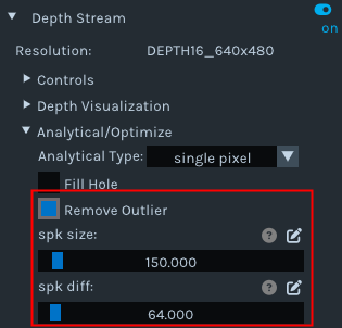
Analytical type of the depth data. For more details, see Analytical Type.
Analytical/Optimize
Fill Hole
For more details, see Fill Hole.
Analytical/Optimize
Remove Outlier
For more details, see Remove Outlier.
Analytical/Optimize
Time Domain Filtering
For more details, see Time Domain Filtering.
Analytical/Optimize
Median Filtering
For more details, see Median Filtering.
Color Stream
Category
Parameter Name
Description
——
Resolution
Format and resolution of the color image.
Controls
analog gain
——
Controls
exposure time
——
Controls
auto exp ctrl
Auto exposure, supported by some camera models only.
Controls
struct aec roi
Auto exposure based on ROI, supported by some camera models only. Left-click the color image and drag the mouse to frame the target area as Region of Interest (ROI). The exposure time and the gain for the entire color image will be automatically adjusted so that the RGB image quality in the ROI is optimized.
Controls
auto white balance
Auto white balance, supported by some camera models only.
Post-Processing
Auto ISP
Software ISP, supported by some camera models only. For details, see Auto ISP.
Post-Processing
Undistort EN
Undistorting function. For details, see Undistort.
Left IR / Right IR Stream
Category
Parameter Name
Description
Controls
undistort
Undistorting function for IR images.
Controls
gain
——
Controls
analog gain
——
Controls
exposure time
——
Controls
flash light enable/flash light intensity
Flash light switch/flash light intensity. For details, see Flash Light.
Controls
hdr/hdr parameter
HDR function switch/ HDR parameters. For details, see HDR.
Click the 2D, 3D, Registration, and Color 3D buttons in the View Switching Area to switch views.
Note
Registration or Color 3D views can only be switched to when both the depth stream and color stream are toggled on.
Place your mouse on the 2D/3D image and adjust the view using the following methods:
Zoom in/out: Scroll the mouse wheel.
Pan (only supported in 3D/Color 3D views): Press and drag the mouse wheel.
Rotate (only supported in 3D/Color 3D views): Press and drag the left mouse button.
Reset the view (only supported in 3D/Color 3D views): Click on
Percipio Viewer supports recording videos while capturing images with a camera. Some parameters can be adjusted during recording, but toggling on/off the data stream is not supported.
To record a video, do the following:
Click on , set the save path for the .bag file and the video recording will start.
By default, the image files are saved in the C drive, but you can also change the storage path according to your preferences.
Switch to the 2D view, click on , select the save path, and click Save.
Switch to the 3D/Color 3D view, click on , select the file format for the 3D point clouds (supports .xyz and .ply formats), select the save path, and click Save.
The function can fill in missing data on a depth image. When used in combination with the “Remove Outlier” function, it can achieve the best results for the depth image.
When the Depth Stream is in status , select Fill Hole, and adjust the parameters k Size and h Size.
Note
If the parameter values of k Size and h Size are set too large, there may be distortion on the depth image.
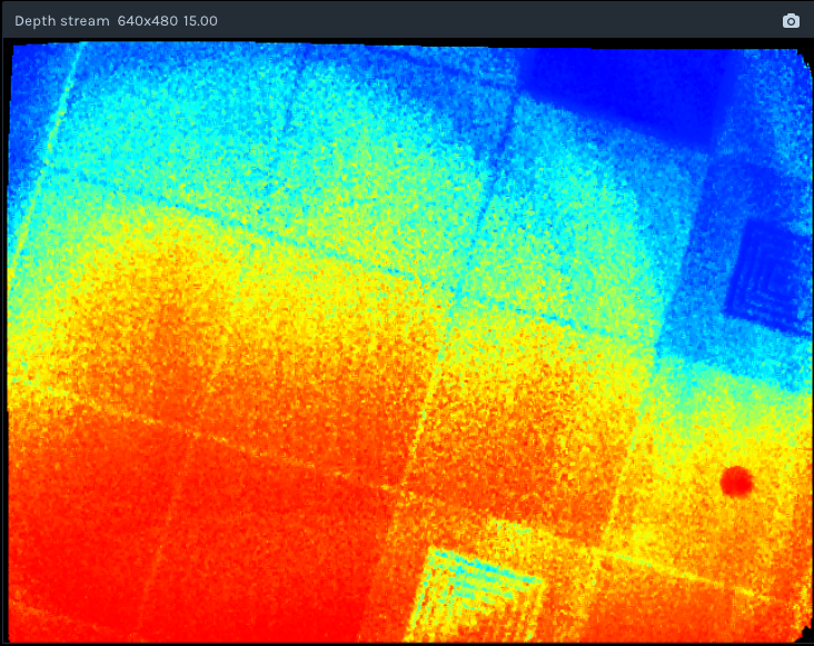
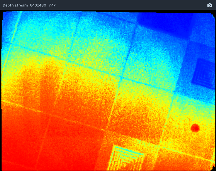
Comparison before and after using the Fill Hole function:
This feature is a post-processing function at the software level for point clouds, which averages multiple frames of data to remove noise and smooth the point cloud.
When the Depth Stream is in status , select Time Domain Filtering, and adjust the time-domain frame count parameter based on the point clouds.
The parameter ‘time-domain frame count’ set to a higher value results in smaller fluctuations in depth values, leading to smoother point clouds.
This feature is a post-processing function at the software level for point clouds, capable of eliminating isolated noise points while preserving as much edge information in the image as possible.
When the Depth Stream is in status , select Median Filtering, and adjust the Ksize parameter based on the point clouds
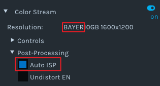
This function is used for post-processing of color images. After the software-level ISP processing, the RAW BAYER images with color deviation can be processed into color images in a normal color space.
Note
Cameras with hardware ISP modules can output color images in a normal color space, and therefore does not need to be post-processed by the Auto ISP function.
When Color Stream is in status , select Auto ISP, and then toggle on the data stream.
The function is software-level data analysis for depth data.
When Depth Stream is in status , select “Analytical Type”.
If you select single pixel, the depth view in the lower left corner displays the following information in real-time:
Depth of center: The depth value of the center of the depth map.
Depth of (X,Y): The depth value of the point indicated by the mouse.
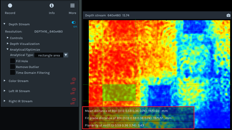
If you select rectangle area, when the left mouse button is dragged on the depth map to draw an area of interest (ROI), the depth view in the lower left corner displays the following information in real-time:
Mean distance of ROI (x1 y1 x2 y2): The average depth value within the ROI area.
Fit plane distance of ROI (x1 y1 x2 y2): The depth distance from the camera’s optical center to the fitted plane of the ROI.
Planarity of ROI (x1 y1 x2 y2): The planarity of the ROI area. The smaller the planarity value, the smoother the depth values within the ROI area.
The following are the image processing functions unique to the ToF series. They can only be set in the interface if the camera is opened with Percipio Viewer.
This function is used to set the modulation channel of the ToF depth camera. Different modulation channels have different modulation frequencies and do not interfere with each other.
When Depth Stream is in status , set tof channel to make sure that the modulation channels of the same series of ToF cameras in the same scene are different.
This function is used to set the threshold for the ToF depth camera to receive the laser modulation intensity. Pixels with modulation intensity below this threshold will not be used to calculate depth, and their depth value will be set to 0.
When Depth Stream is in status , modify tof modulation threshold based on the real-time depth image.
This function is used to set the jitter filtering threshold for the ToF depth camera. The larger the threshold value, the less depth data jitter on the depth image’s edge is filtered.
When Depth Stream is in status , modify tof jitter threshold based on the real-time depth image to filter out jittered pixels on the edge.
This function is used to optimize the quality of the depth image in high-contrast scenes. Currently, only TL460-S1-E1 in the ToF series support this function.
To set up the HDR Ratio, do the following:
When all data streams are in status , click on and select a trigger mode as needed.
Hardware Trigger Mode
Software Trigger Mode (continue)
Software Trigger Mode (single)
When Depth Stream is in status , set depth quality to high.
When Depth Stream is in status , adjust HDR ratio in real time based on the depth image.
The following are the image processing functions unique to the PS series. They can only be set in the interface if the camera is opened with Percipio Viewer.
The SGBM parameters are used to adjust the camera’s measuring range, accuracy, frame rate, and used in post-processing of the depth image. Currently, only PS800-E1 supports the adjustment of these parameters.
To adjust the SGBM parameters, expand the Control parameters of the Depth Stream when all data streams are in status and no other functions are enabled.
SGBM Parameters Related to Range, Accuracy, and Frame Rate
scale unit
This parameter is used to set the unit of pixel values in the depth image.
The maximum depth value is equal to 65536 * scale unit.
The smaller the set value of this parameter, the higher the accuracy of the depth calculation. However, if the set value is too small, it may lead to errors in the depth calculation.
disparity num
This parameter is used to set the range of the disparity search.
The larger the set value of this parameter, the greater the measurement range in the camera’s Z direction, but it also consumes more computational resouces. It is recommended to set it to a multiple of 16.
disparity offset
This parameter is used to set the starting value of the disparity search.
The smaller the set value of this parameter, the larger the maximum measured value in Z-direction (Zmax), which means a greater measurement range in the camera’s Z direction. The lower limit of the disparity offset is affected by depth of field.
match window height
This parameter is used to set the height of the disparity matching window.
The value must be odd.
match window width
This parameter is used to set the width of the disparity matching window.
The value must be odd.
The larger the matching window (match window height * match window width), the smoother the depth image, but the accuracy is also lower. The smaller the disparity matching window, the more details are displayed in the depth image, but the probability of mismatching is higher.
image number
This parameter is used to set the number of IR images used for depth calculation.
The larger the set value of this parameter, the better the image quality for the depth image, but the frame rate is also lower.
Note
Due to the influence of camera computing power, there is a constraint between IMAGE_NUM and MATCH_WIN_HEIGHT. You can check the constraint relationship in configuration information of the camera. For the ways of obtaining the file, please refer to Note.
SGBM Parameters Related to Smoothing of Edge Pixels in the Image
Semi-global param p1
This parameter is the constraint penalty on the disparity change by +/-1 between neighbor pixels.
The larger the set value of this parameter, the smoother the depth image.
This parameter is set to prevent discontinuous or unreasonable depth values, so as to effectively suppress noise and discontinuity.
Semi-global param p1 scale
This parameter is another constraint penalty on the disparity change by +/-1 between neighbor pixels.
The smaller the set value, the smoother the depth image.
semi-global param p2
This parameter is the constraint penalty on disparity changes to be greater than 1 between neighbor pixels.
The larger the set value of this parameter, the smoother the depth image. It is important to note that the algorithm requires P2>P1.
This parameter is set to effectively handle texture-rich areas and reduce the number of mismatches.
enable half window size
This is the switch for searching filters. The search filters can further optimize the depth image, removes noise and discontinuity, and is more friendly to edge point clouds.
SGBM Parameters Related to Mismatch
uniqueness factor param
This parameter is used to set the uniqueness check parameter 1, which is margin in percentage by which the best (minimum) computed cost function value should “win” the second best value to consider the found match correct.
The larger the set value of this parameter, the more unique the matching cost, and the more mismatched points are filtered out.
uniqueness min absolute diff
This parameter is used to set the uniqueness check parameter 2, which is margin in difference by which the best (minimum) computed cost function value should “win” the second best value to consider the found match correct.
The larger the set value of this parameter, the more unique the matching cost, and the more mismatched points are filtered out.
enable LRC
This is the switch for left-right consistency check (LRC). After enabling “enable LRC”, adjust the parameter “max LRC diff”.
During stereo matching, for the pixels on the same object surface, use LR to denote the disparity between the left image and the right image, and RL to denote the disparity between the right image and the left image. When ABS(LR-RL) < max LRC diff, the point is considered a reliable match point.
The smaller the set value of “max LRC diff”, the more reliable the matching result.
Median Filter
Median Filter
This is the switch for median filter. The median filter is used to eliminate isolated noise points while preserving the edge information of the image as much as possible. After enabling “enable median filter”, adjust the parameter “median filter thresh”.
The larger the set value of “median filter thresh”, the more noise points are filtered out, but it may also cause the loss of detailed information in the depth image.
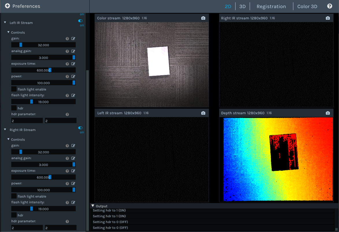
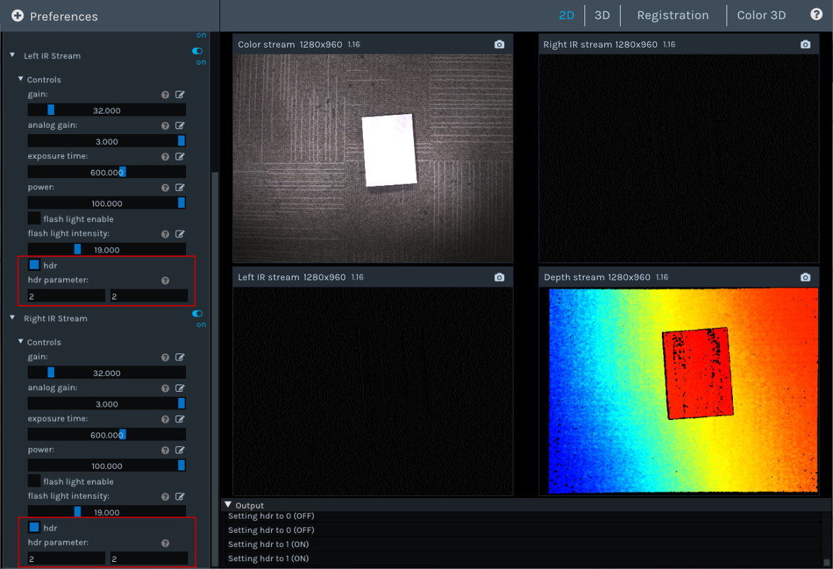
This function is used to optimize the quality of the depth image in high-contrast scenes. After setting the HDR parameters, it is necessary to adjust the exposure time of the Left/Right IR to obtain the best quality of the depth image.
To set up the HDR function, do the following:
When both Left IR Stream and Right IR Stream are in status , select hdr, set Parameter 1 and Parameter 2, and then press Enter to confirm the settings.
Tip
The setting range for parameter 1 and parameter 2 is 0, 1, 2.
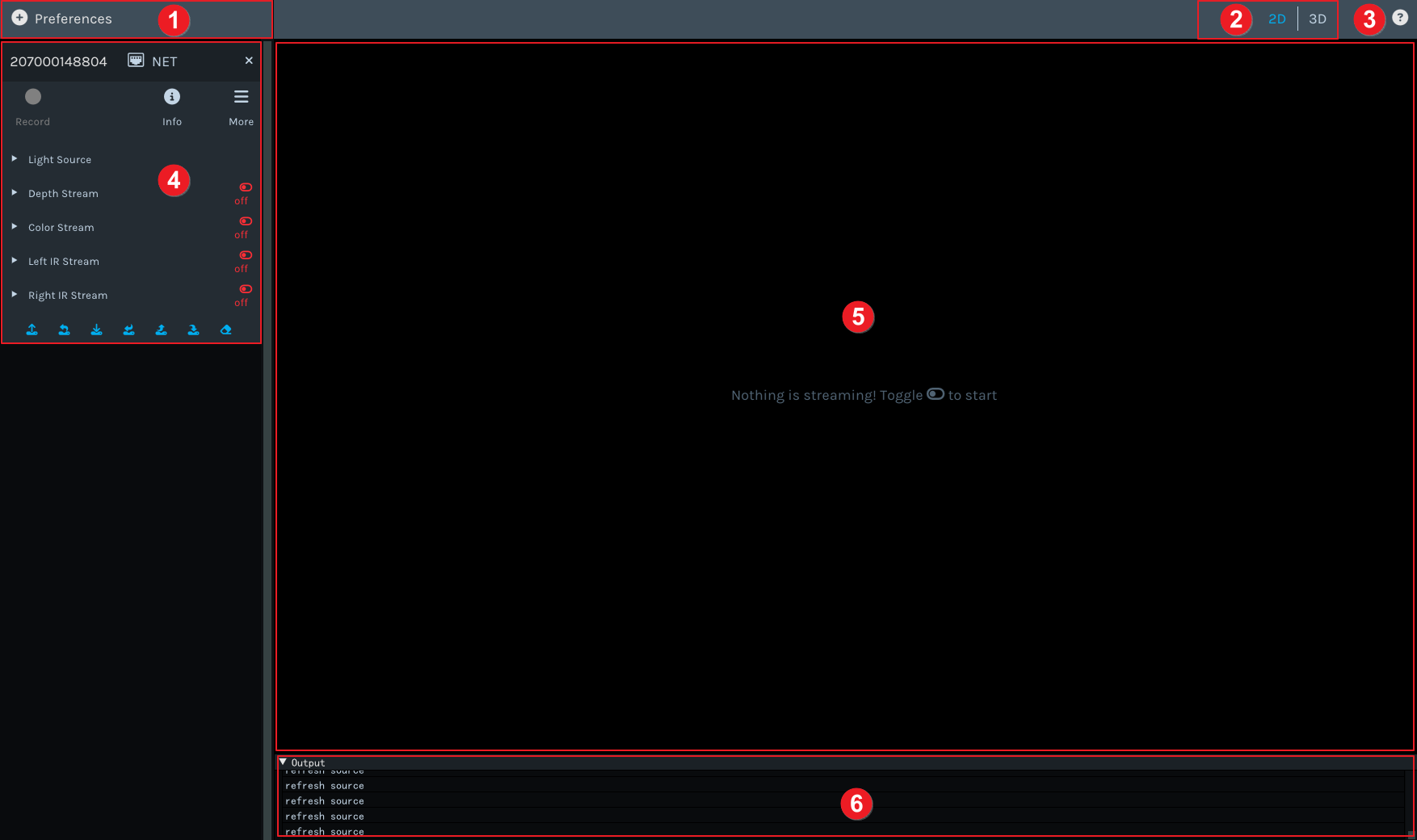
 Button: Go to the Percipio Viewer User Guide page.
 indicates that the data stream is toggled on.
 indicates that the data stream is toggled off.

 on the left side of the data stream, and adjust parameters according to actual needs.

 , set the save path for the
 to end the video recording.
 , select the save path, and click Save.
 , select the file format for the 3D point clouds (supports


 and select a trigger mode as needed.