Hardware Connections
This section mainly introduces the camera’s power supply methods, the connection methods between the camera and the computer, and the principles and examples of providing external trigger signals to the camera.
Important
For safety precautions regarding hardware connections, please refer to the Safety Instructions for more details.
Camera Power Supply Methods
Typically, there are two power supply methods for Percipio cameras:
Using External DC Power Supply
Connect the external DC power source to the camera using a DC power cable. One end of the cable plugs into the camera’s power connector, and the other end connects to the external DC power source.
When using a regulated voltage source, it is recommended to select a regulated power supply with channel switching capability to prevent voltage fluctuations during direct power-on/off operations from propagating to the load.
For the camera’s DC power supply voltage requirements, please refer to Product Specifications of the specific camera model.
Using PoE (Power over Ethernet) Switch
Connect the PoE switch to the camera via the camera’s Gigabit Ethernet cable. One end of the cable plugs into the camera’s data connector, and the RJ45 connector is inserted into the RJ45 port of the PoE.
Please use a standard-compliant PoE switch to power the camera. For the standard requirements of PoE switch, please refer to Product Specifications of the specific camera model.
Note
Some camera models do not support being powered up via the POE switch.
Network Connection Methods
Percipio network cameras are factory-set to use the DHCP method to dynamically obtain an IP address from the server.
Before connecting the camera to a computer, ensure that the computer’s network card is set to automatically obtain an IP address (DHCP).
Network Connection Method 1
Network Connection Method 1
Connect the camera directly to the computer’s Gigabit Ethernet connector using a Gigabit Ethernet cable.
About one minute after the camera is powered on, the computer and the camera can successfully negotiate and obtain an IP address in the 169.254.xx.xx network segment.
Use the SDK sample program ListDevices.exe to list the camera and check if it has obtained an IP address of the desired network segment.

Network Connection Method 1
Network Connection Method 2
Connect the camera and computer to the same Gigabit Ethernet switch using Gigabit Ethernet cables.
About one minute after the camera is powered on, the computer and the camera can successfully negotiate and obtain an IP address in the 169.254.xx.xx network segment.
Use the SDK sample program ListDevices.exe to list the camera and check if it has obtained an IP address of the desired network segment.
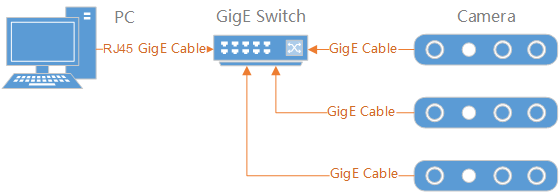
Network Connection Method 2
Network Connection Method 3
Connect the camera and computer to the same Gigabit Ethernet switch using Gigabit Ethernet cables. Connect the switch to a router that supports DHCP service, or establish a DHCP server within the local area network.
About one minute after the camera is powered on, the computer and the camera can obtain an IP address from the DHCP address server in the 192.168.xx.xx network segment.
Use the SDK sample program ListDevices.exe to list the camera and check if it has obtained an IP address of the desired network segment.
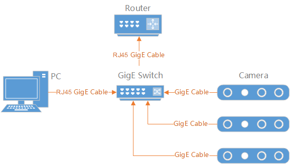
Network connection method 3
Note
If you need to modify the IP address of the camera, please refer to Application Example: Set Camera IP.
Hardware Trigger Connection Methods
This section mainly introduces how to connect an external hardware trigger signal to the camera from the aspects of trigger principle, requirements of the trigger signal and connection references.
Trigger Principle
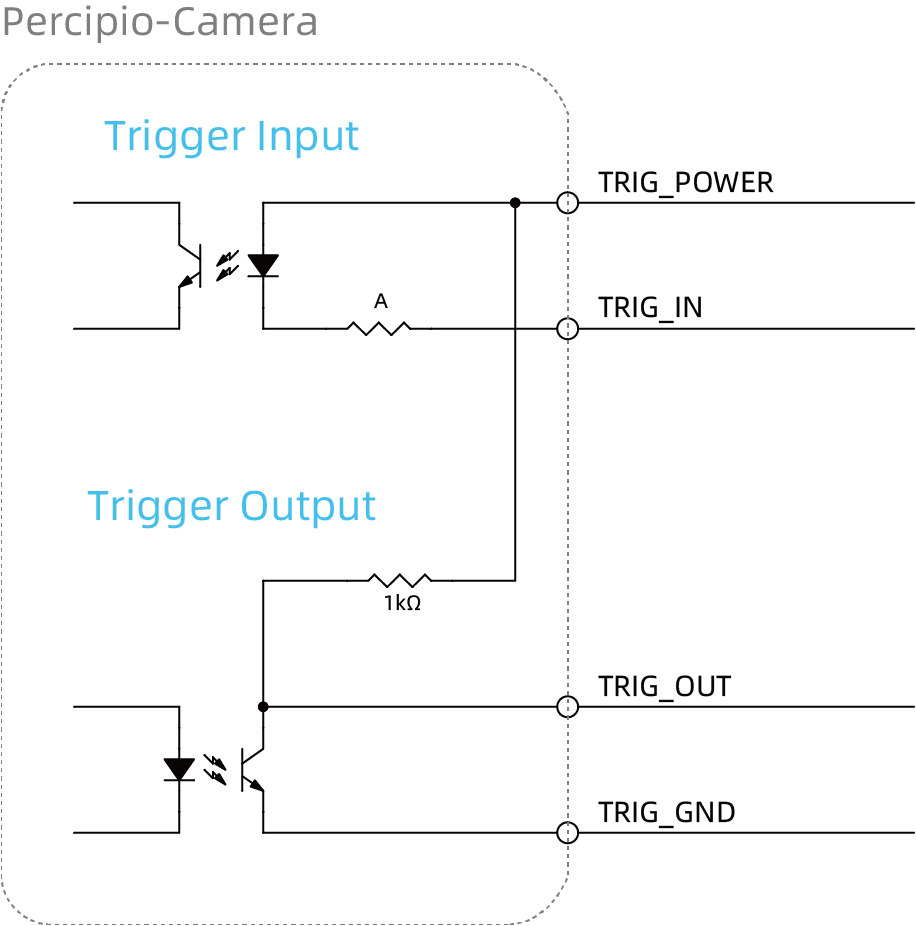
The camera trigger connector uses optocouplers for electrical safety isolation. The internal schematic diagram for hardware trigger is shown below. The camera already has integrated current-limiting resistors, so there is no need to connect external current-limiting resistors when using it.
Note
Hardware trigger has two types: rising-edge trigger and falling-edge trigger. For information on the hardware trigger types supported by different models of Percipio cameras, please refer to Product Specifications.
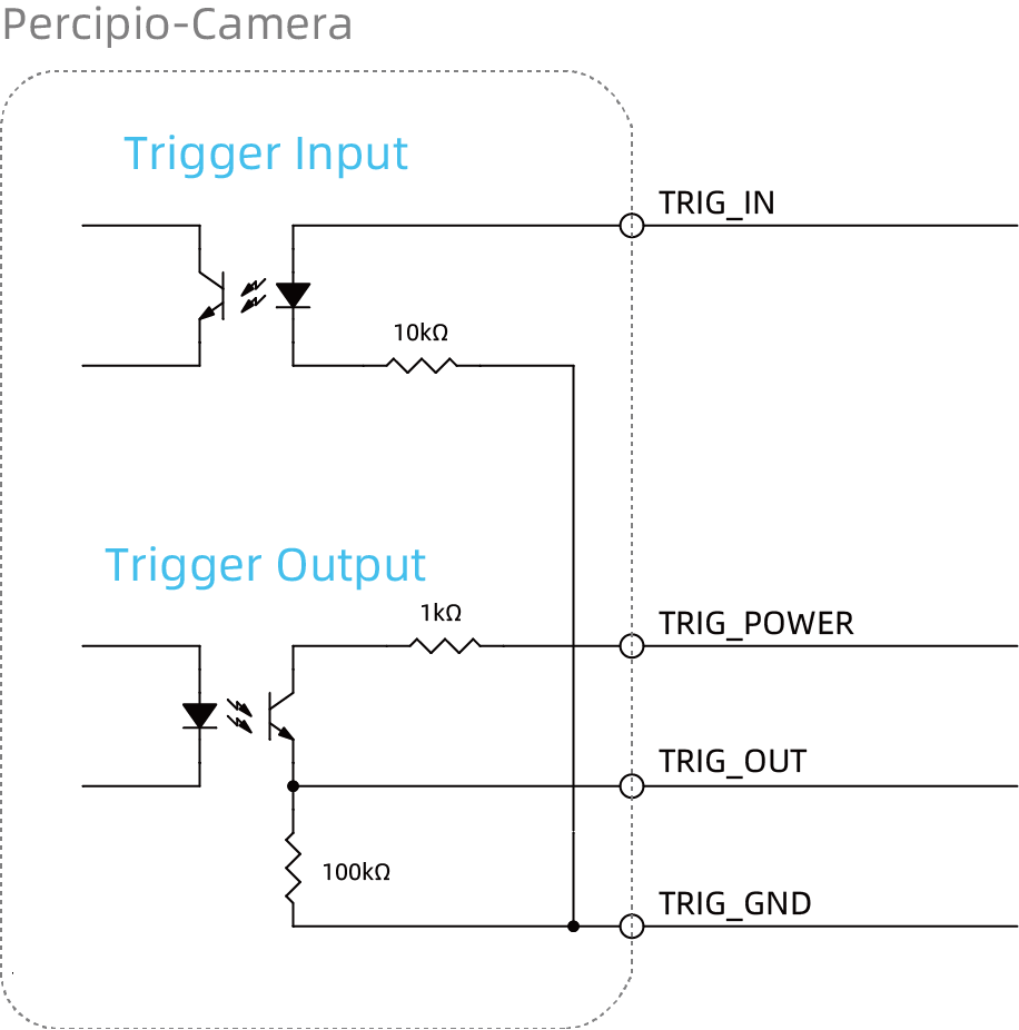
For cameras of falling-edge trigger type, the built-in resistor A of TL460-S1-E1 is 4.7kΩ, while the built-in resistor A of the other cameras is 10kΩ.
Requirements of the Trigger Signal Input
The trigger signal input should meet the following requirements:
For cameras of rising-edge trigger type, the trigger input is required to be a high pulse square wave signal, with the rising edge being effective and the pulse width ranging from 10 to 30 milliseconds. To avoid false trigger, the signal’s rising time should not exceed 5 microseconds.
For cameras of falling-edge trigger type, the trigger input is required to be a low pulse square wave signal, with the falling edge being effective and a pulse width ranging from 10 to 30 milliseconds. To avoid false trigger, the signal’s falling time should not exceed 5 microseconds.
The trigger frequency must not exceed the device’s processing capability (which is the frame rate in continuous capture mode), otherwise the camera will discard the trigger signal and not process it.
Wiring References for Trigger Input
Rising-Edge Trigger Input
For cameras of rising-edge trigger type, the client needs to use a connector of PNP (source type) type to control the trigger. A wiring reference diagram is shown below. The voltage of the trigger power, unless otherwise specified, can be DC 12V~24V. The client’s output connector should be connected to the TRIG_IN signal line, and the TRIG_OUT signal line can be used as needed.

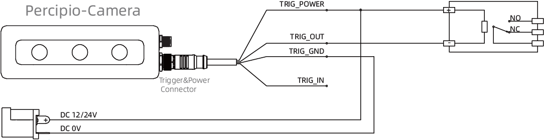
For cameras of rising-edge trigger type, the client can also use a relay to control the trigger. A wiring reference diagram is shown below. The voltage of the trigger power, unless otherwise specified, can be DC 12V~24V. The client’s output connector should be connected to the TRIG_IN signal line, and the TRIG_OUT signal line should be used as needed.
Falling-Edge Trigger Input
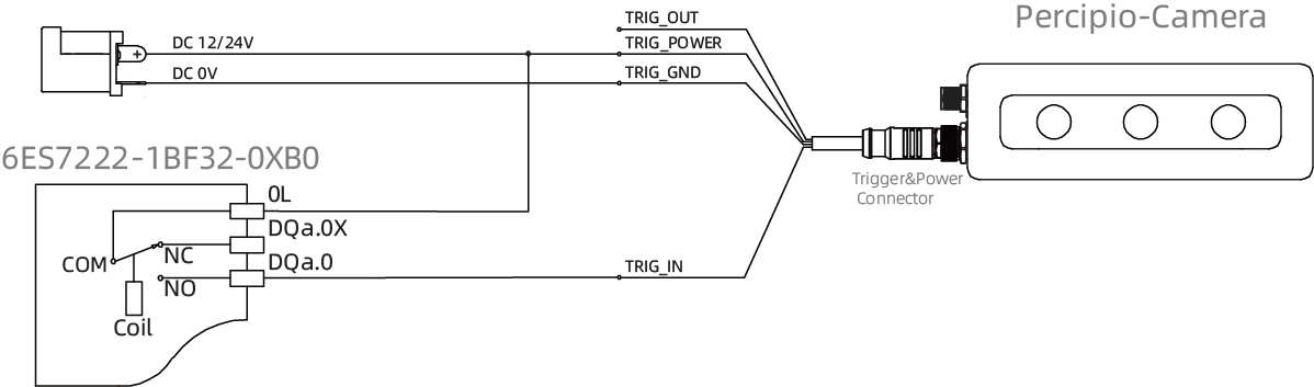
For cameras of falling-edge trigger type, the client can use a connector of NPN (sink type) type to control the trigger. A wiring reference diagram is shown below. The voltage of the trigger power, unless otherwise specified, can be DC 12V~24V. The client’s output connector should be connected to the TRIG_IN signal line, and the TRIG_OUT signal line should be used as needed.

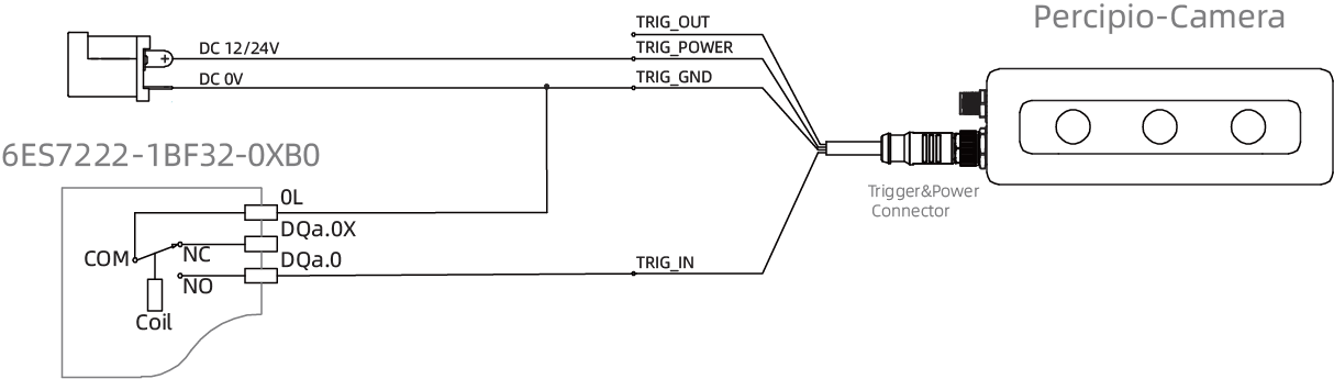
For cameras of falling-edge trigger type, the client can use a relay to control the trigger. A wiring reference diagram is shown below. The voltage of the trigger power, unless otherwise specified, can be DC 12V~24V. The client’s output connector should be connected to the TRIG_IN signal line, and the TRIG_OUT signal line should be used as needed.
Connection References for Trigger Output
Rising-Edge Trigger Output
The rising-edge output signal of the camera can trigger the optocoupler. A wiring reference diagram is shown below, where RL is selected based on the trigger power.
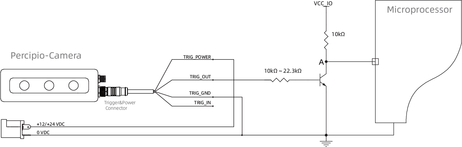
The rising-edge output signal of the camera can be connected to the microprocessor as a logic signal. A wiring reference diagram is shown below.
For microprocessors, the camera trigger output has a higher voltage (12V~24V) when it is at a high level. The diagram below uses an NPN transistor to convert the camera trigger output level to the IO voltage required by the microprocessor before inputting it to the microprocessor. When the camera has rising-edge trigger output, the voltage is 12V~24V, and the NPN transistor conducts, pulling the voltage at point A down to 0V, which is then inputted to the microprocessor as a low level. Therefore, when the microprocessor detects a low level, it indicates that the camera has a trigger signal output.
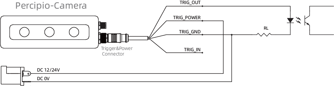
Falling-Edge Trigger Output
The falling-edge output signal of the camera can drive the optocoupler. A wiring reference diagram is shown below, where RL is selected based on the trigger power.

The falling-edge output signal of the camera can drive a relay with a low rated operating current (within the range of 10mA). A wiring reference diagram is shown below, using the DELIXI CDG1-1DD/10A relay as an example.
The falling-edge output signal of the camera can be used as a logic signal input to the microprocessor. A wiring reference diagram is shown below.
For microprocessors, the camera trigger output has a higher voltage (12V~24V) when it is at a high level. The diagram below uses an NPN transistor to convert the camera trigger output level to the IO voltage required by the microprocessor before inputting it to the microprocessor. When the camera has falling-edge trigger output, the voltage is 0V and the NPN transistor is turned off, pulling the voltage at point A to VCC_IO, which is then inputted to the microprocessor as a high level. Therefore, when the microprocessor detects a high level, it indicates that the camera has a trigger signal output.
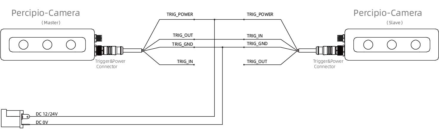
Wiring Reference for Camera Cascade
For working scenario of camera cascade triggering (Master-Slave mode), please refer to the wiring diagram shown in the following figure.
Note
The trigger output connector of the master camera has limited current output capability. It is recommended to use a Trigger Hub when using more than 2 slave cameras.