Hand-Eye Calibration Tool
Click the Hand-Eye Calibration Tool in the menu bar to open the hand-eye calibration tool window.

Introduction to Hand-Eye Calibration
Hand-eye calibration refers to the process of calculating the transformation matrix between the camera and the robot coordinate system after the camera is installed. This is used to convert point cloud data from the camera coordinate system to the robot coordinate system. Depending on the camera installation method, hand-eye calibration is divided into two scenarios:
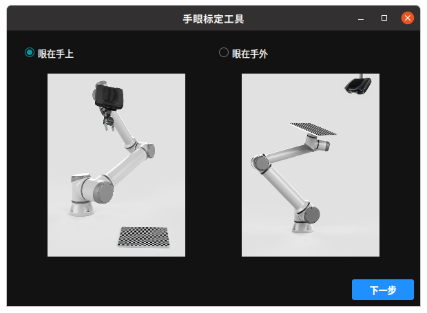
EyeInHand: The camera is installed on the robot arm’s end, and the calibration board remains fixed. The robot arm changes its pose to capture images of the calibration board, calibrating the transformation matrix between the camera and the robot arm’s end coordinate system.
EyeToHand: The camera is fixed (e.g., mounted on the ceiling), and the calibration board is fixed on the robot arm. The robot arm changes its pose, and the camera captures images of the calibration board in different poses, calibrating the transformation matrix between the camera and the robot base coordinate system.
Introduction to Robot Types
When selecting the robot type, the following two types are included:
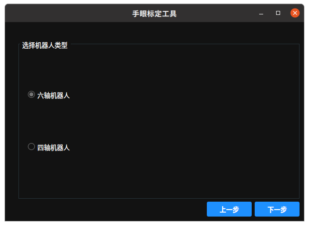
Six-Axis Robot: Has six degrees of freedom and can perform complex path planning and pose adjustments in three-dimensional space. Suitable for tasks requiring high precision and flexibility, such as welding and assembly.
Four-Axis Robot: Has four degrees of freedom and is known for its fast operation speed and simple structure. Suitable for simple planar tasks such as handling, palletizing, and packaging.
Introduction to Calibration Modes
When selecting the calibration mode, the following two methods are included:
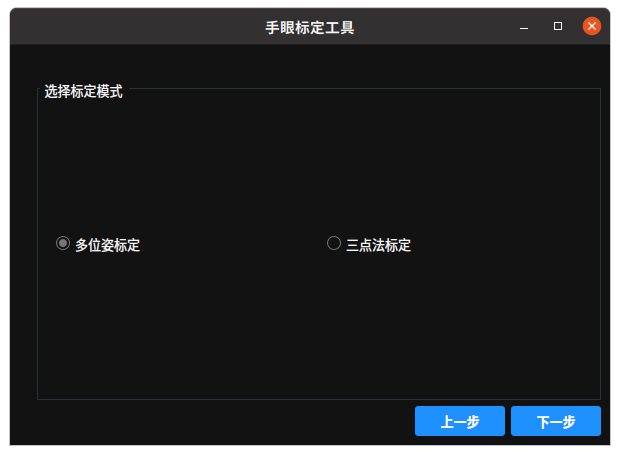
Multi-Pose Calibration: Improves calibration accuracy by collecting data in multiple different poses. Suitable for high-precision scenarios.
Three-Point Calibration: Uses three known points for quick calibration. The method is simple and efficient, suitable for scenarios with lower accuracy requirements and rapid deployment.
Camera Setup
The camera setup interface is used to connect the camera, adjust camera parameters, and configure calibration parameters.

Camera Parameters
Device List: Displays the currently available camera devices. Click theSearch Devicesbutton to refresh and view all connected cameras.Color Image Mode: Select the mode for capturing color images.Depth Image Mode: Select the mode for capturing depth images.Calibration Image:Color: Use color images for calibration.
LeftIR: Use left infrared images for calibration.
Laser Auto Control: Controls the laser’s working mode.Yes: Laser intensity is automatically adjusted based on the environment.No: Manually set the laser intensity.
Laser Intensity: Set the laser intensity. Range: [0,100].Color Auto Exposure: Color auto exposure mode.Yes: The camera automatically adjusts exposure to adapt to lighting conditions.No: Manually set the exposure value.
Color Exposure Value: When color auto exposure is off, manually set the color camera’s exposure value to adjust image brightness.
Calibration Parameters
Calibration Type:N-Image Calibration: Use depth and color images for calibration to improve accuracy and stability. Suitable for high-precision scenarios.Color Image Calibration: Use color images for calibration.
Depth Acceptance Rate: The proportion of valid depth data in the depth image.
Set Calibration Board
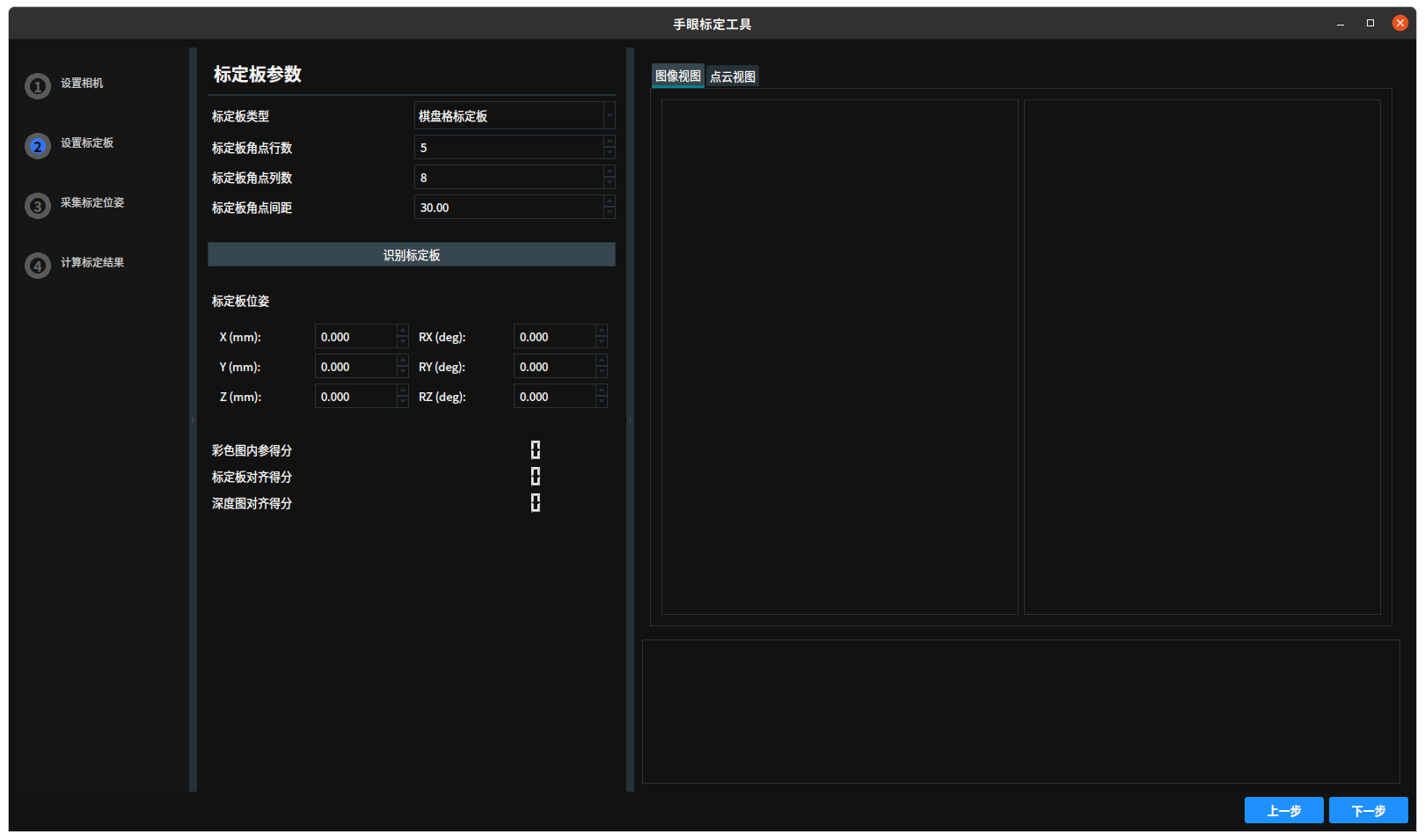
Calibration Board Parameters
Calibration Board Type:When selecting Chessboard Calibration Board, set the following parameters:
Calibration Board Corner Rows: The number of corners in the vertical direction of the chessboard.Calibration Board Corner Columns: The number of corners in the horizontal direction of the chessboard.Calibration Board Corner Spacing: The physical distance between adjacent corners, in mm.
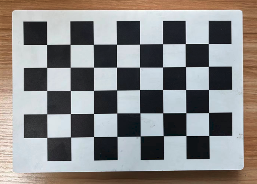
Chessboard Calibration Board
When preparing the chessboard calibration board, confirm the following:
The number of rows and columns of the chessboard should be one odd and one even.
Confirm the size of the chessboard.
Ensure the area of the chessboard fits within the camera’s field of view.
Below are example images of calibration boards supported by RVS hand-eye calibration.
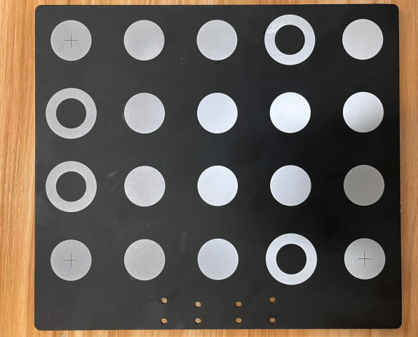
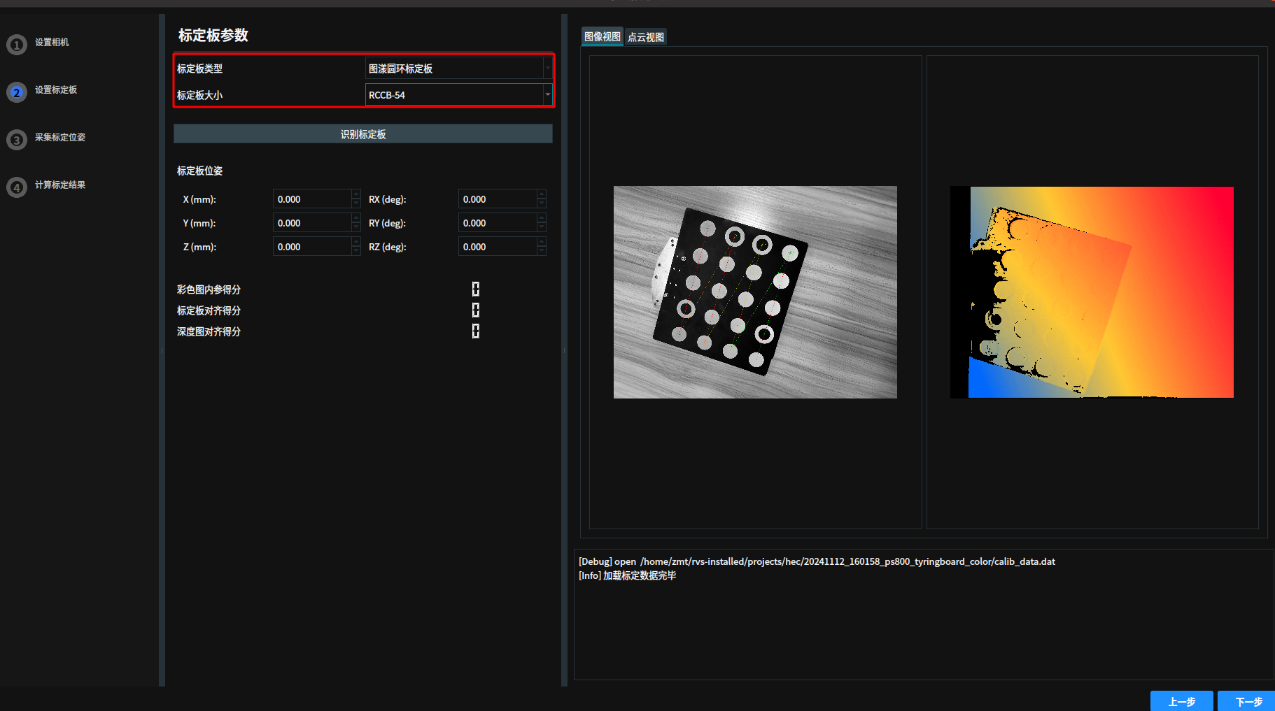
Tyto Ring Calibration BoardWhen selecting
Tyto Ring Calibration Board, set the following parameters:Calibration Board Size: Choose from the following sizes:RCCB-28: The distance between adjacent circle centers is 28 mm.
RCCB-54: The distance between adjacent circle centers is 54 mm.
RCCB-88: The distance between adjacent circle centers is 88 mm.
RCCB-140: The distance between adjacent circle centers is 140 mm.
Example images of Tyto Ring Calibration Board:
Identify Calibration Boardbutton: Click to automatically identify feature points on the calibration board (e.g., chessboard corners or ring centers).Calibration Board Pose: The position and orientation of the calibration board in the camera’s field of view.Color Image Intrinsic Score: Evaluates the accuracy of the color camera’s intrinsic calibration.Calibration Board Alignment Score: Evaluates the accuracy of calibration board recognition and alignment in the image.Depth Image Alignment Score: Evaluates the alignment accuracy between the depth image and the calibration board.Previous: Click to go back to theSet Camerainterface.Next: Click to proceed to theCapture Calibration Posesinterface.
Capture Calibration Poses
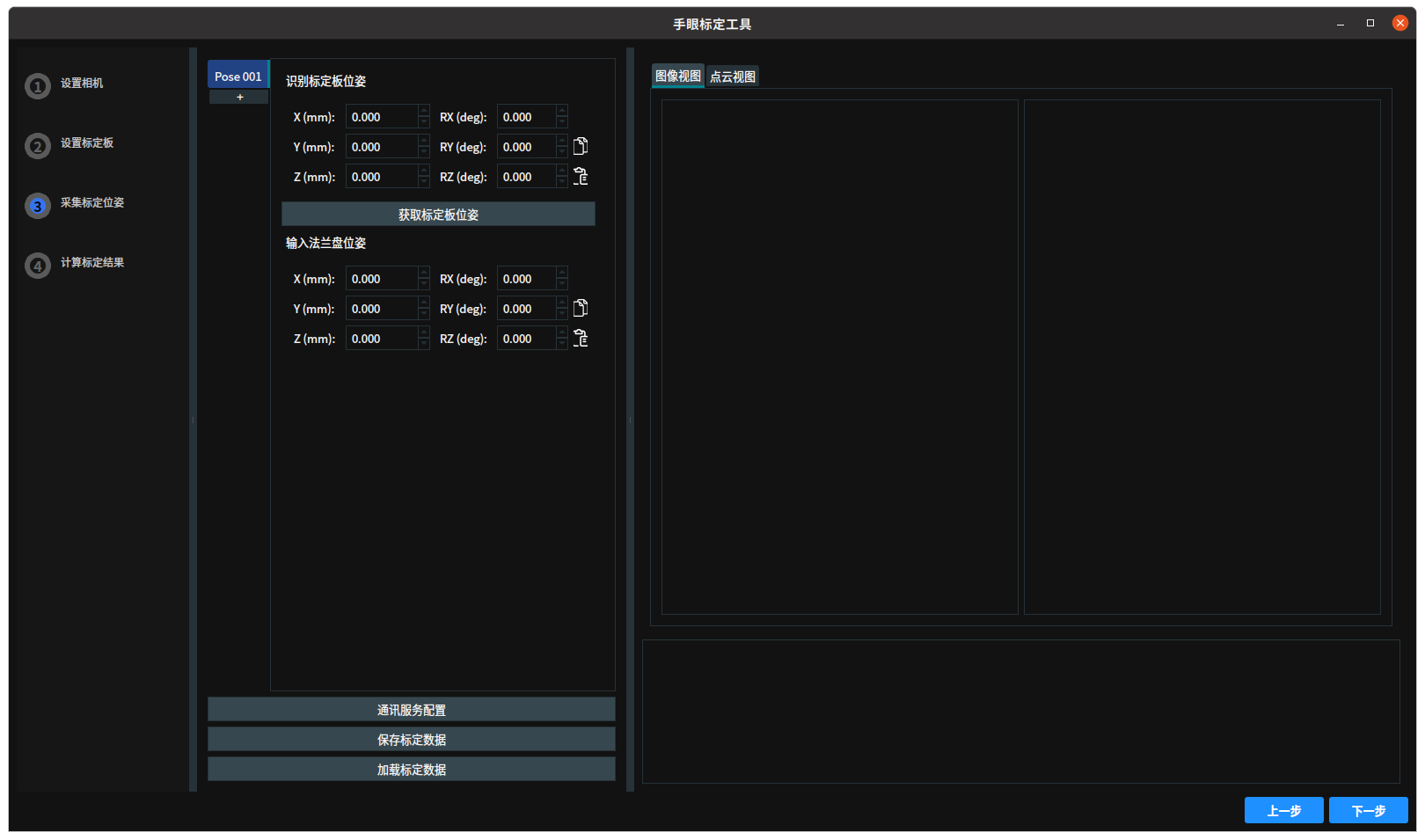
Pose 001: A set of poses during the calibration process.Identify Calibration Board Pose: The position and orientation of the calibration board in the camera’s field of view.Get Calibration Board Posebutton: Click to obtain the calibration board pose.Input Flange Pose: The flange pose sent by the robot. If communication is not used, manually input the flange pose.Communication Service Configuration:Port: The port number the server listens to.Separator: Used to split the received data into an array and assign it to Pose or JointArray data. The data separator is a string type, so you can use “ “ (space), “abc” (any string), or “!@#$%” (any common characters).Start: Start the communication service, allowing the server to listen and process requests.Stop: Stop the communication service.Reply Message: The response message sent by the server after receiving a request.Server Status: Displays the current server’s running status (e.g., started or stopped) and the received and replied messages.Auto Trigger: When checked, automatically add a set of poses.
Save Calibration Data: Save the current calibration results to a file or database for later use.Load Calibration Data: Load previously saved calibration results from a file.Previous: Click to go back to theSet Calibration Boardinterface.Next: Click to proceed to theCalibration Resultsinterface.
Calculate Calibration Results
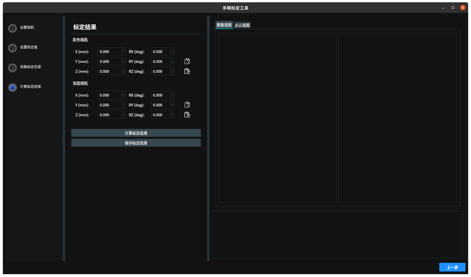
Calibration Results
Color Camera: Output the color camera calibration parameters.Depth Camera: Output the depth camera calibration parameters.Calculate Calibration Results: Click to calculate the calibration results.Save Calibration Results: Click to save the calibration results to the specified directory.Calibration Full Corner RMSE (mm): The root mean square error of all corner positions measured by the camera compared to their true positions. This value should be within a reasonable range, depending on the application scenario and device accuracy requirements.Previous: Click to go back to theCalculate Calibration Positioninterface.
Hand-Eye Calibration Demonstration
Chessboard Hand-Eye Calibration
Use the Chessboard Calibration Board for EyeToHand installation of a six-axis robot with multi-pose hand-eye calibration.
Calibration Configuration
Open the
Hand-Eye Calibration Tool, select the calibration scenario, robot type, and calibration mode.Calibration Scenario: EyeToHand, click
Next.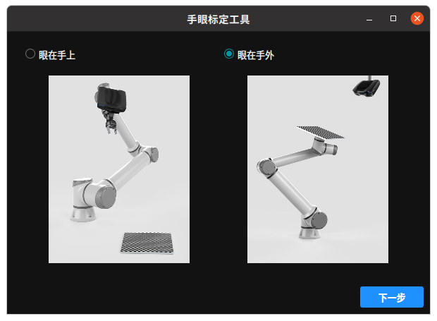
Robot Type: Six-Axis Robot, click
Next.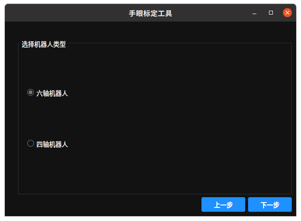
Calibration Mode: Multi-Pose Calibration, click
Next.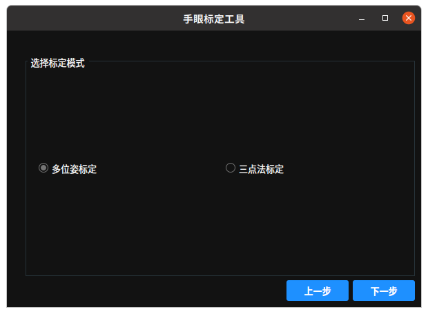
Set Camera
Enter the
Set Camerainterface. Click theSearch Devicesbutton to find the camera that needs hand-eye calibration.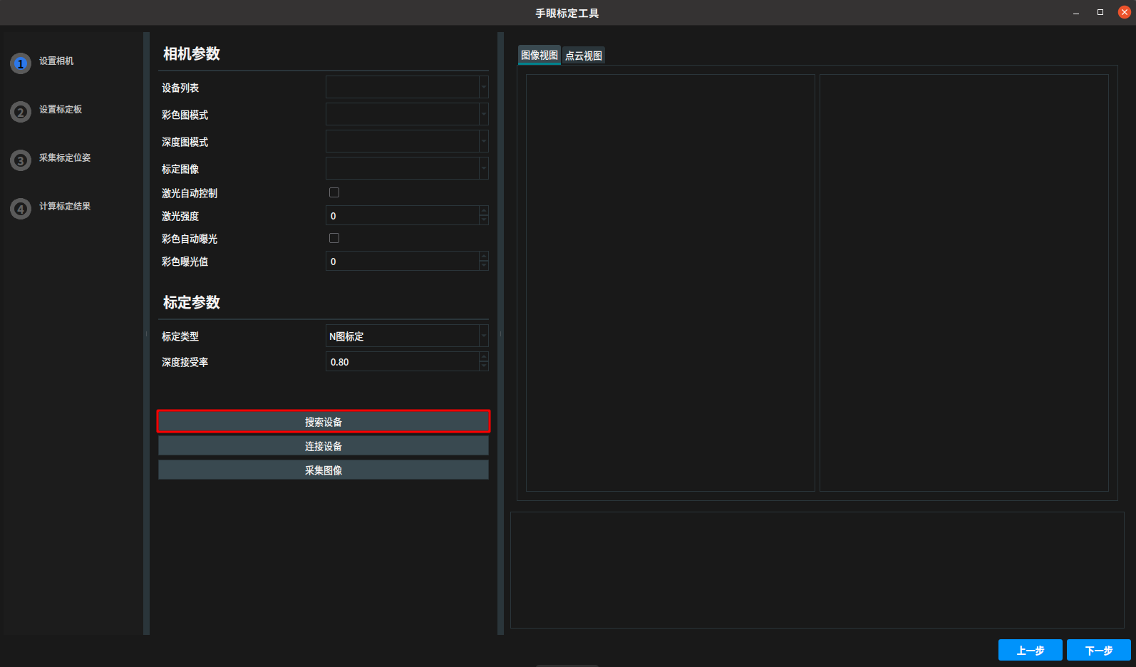
The log bar displays a successful camera search, and the device list shows the searched devices.
If the connection fails, please refer to What to Do If RVS Cannot Connect to the Camera?
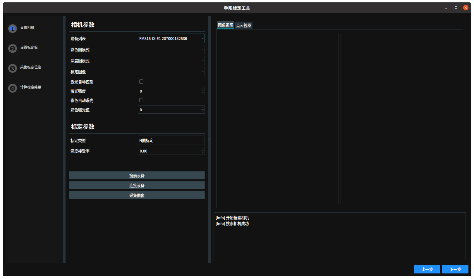
Click the
Connect Devicebutton. After successfully connecting the camera, the camera parameters are displayed in the camera parameter bar.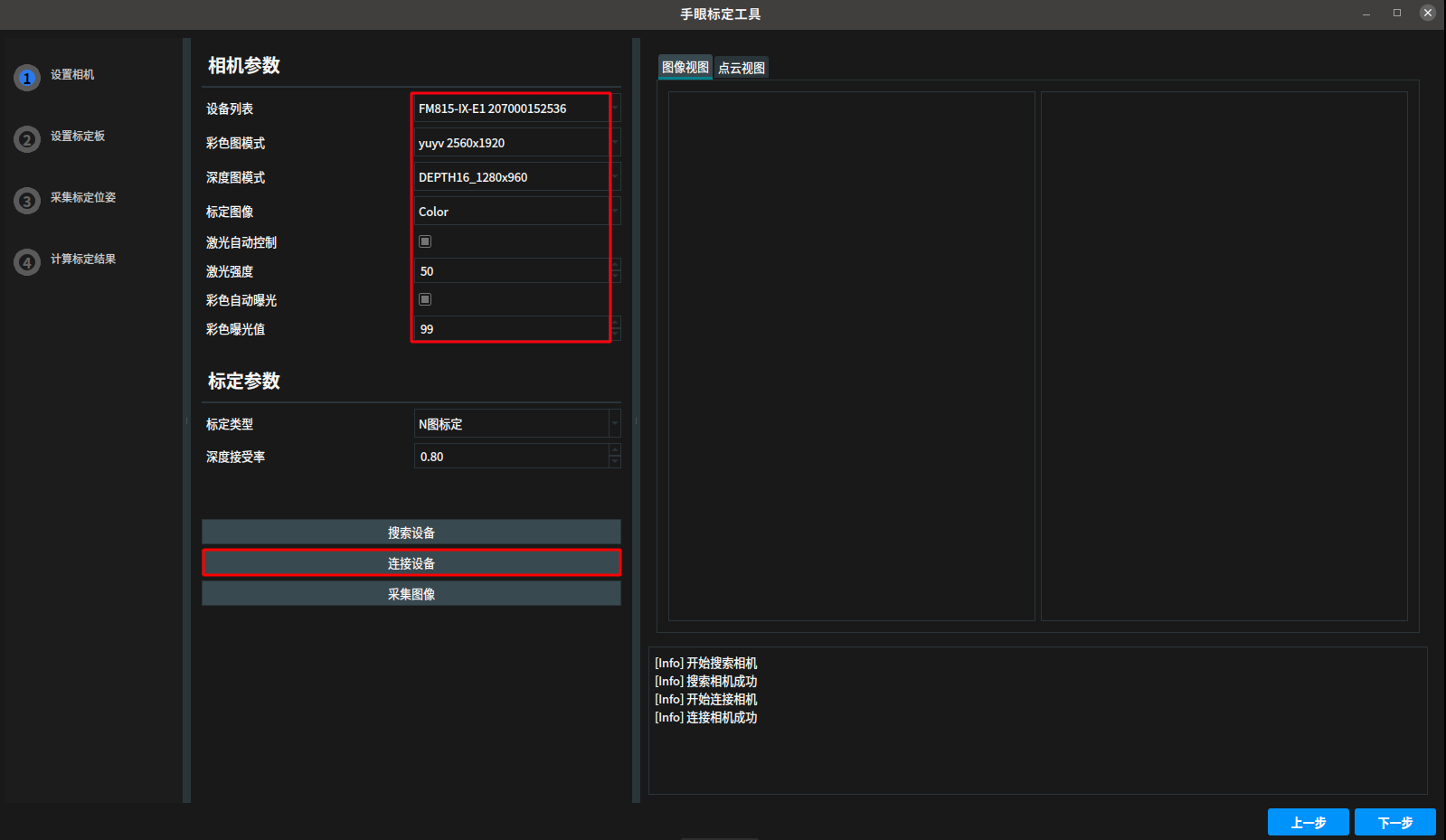
Click
Capture Imageto display the captured color and depth images in the view. If the image quality is not ideal, adjust the laser intensity and color exposure value in the camera parameter bar to optimize the results. Also, set the parameters in the calibration parameter bar for subsequent calibration operations.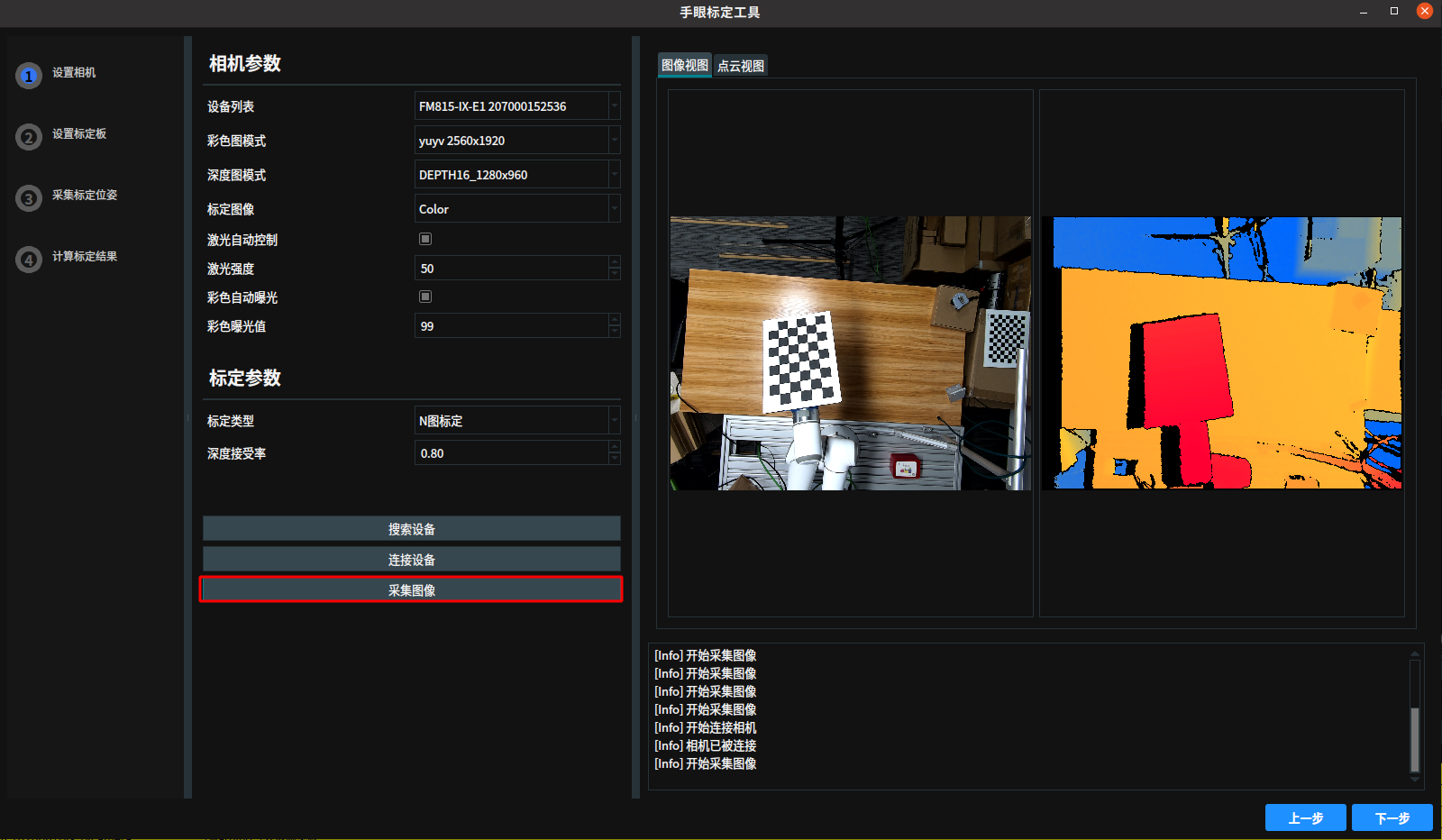
Set Calibration Board
After setting the camera and calibration parameters, click
Nextto set the calibration board.Enter the
Set Calibration Boardinterface and set the parameters:Calibration Board Type: Chessboard Calibration Board
Calibration Corner Rows: 5
Calibration Corner Columns: 8
Calibration Corner Spacing: 30
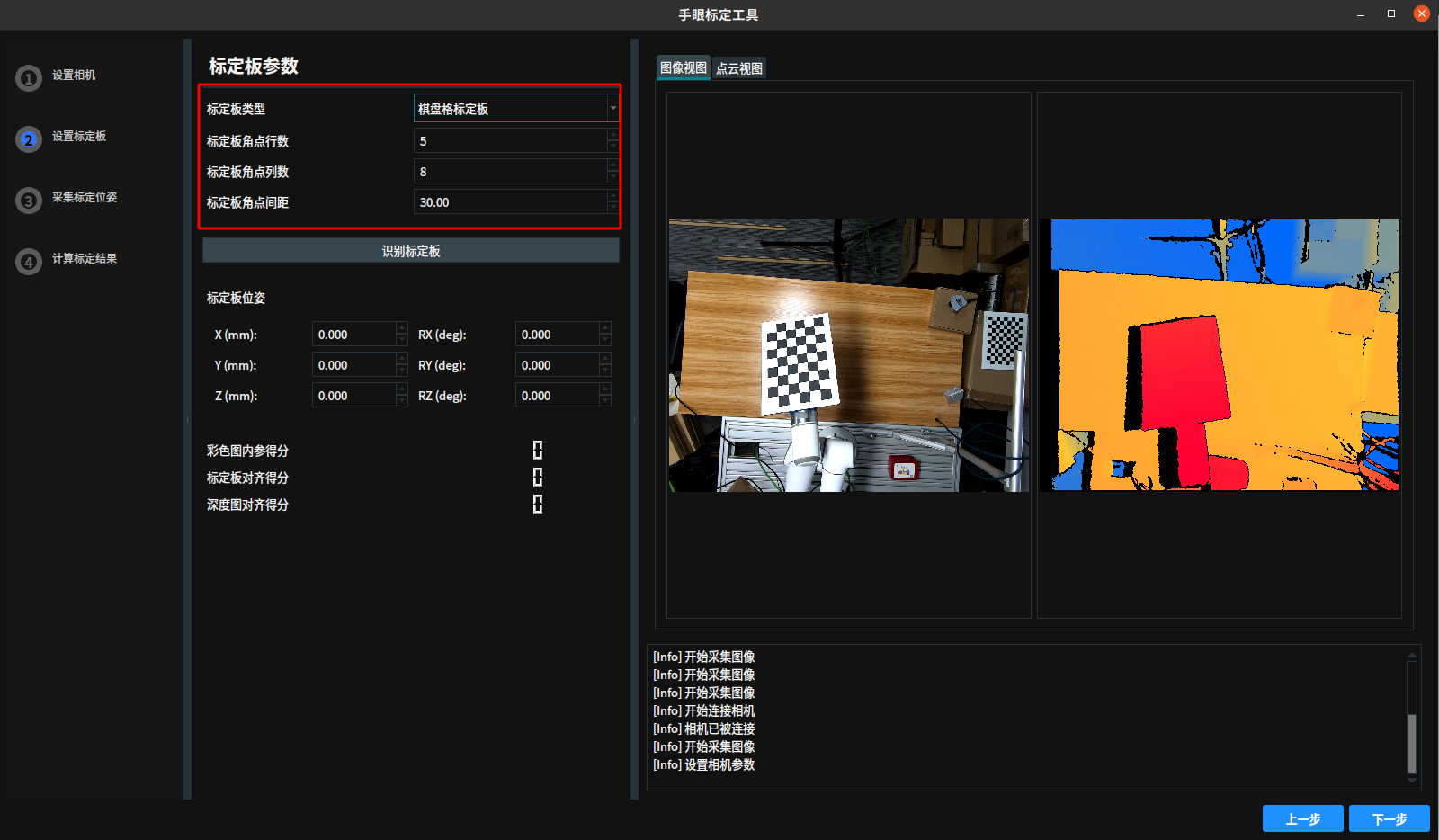
Click the
Identify Calibration Boardbutton to obtain the calibration board pose.View Point Cloud: Switch to the
Point Cloud Viewto compare the 3D point cloud of the calibration board with the calibration board information (corners or reference plane) to verify the accuracy of the calibration results.Check Scores:
Color Image Intrinsic Score: Should be above 90.
Calibration Alignment Score: Should be above 90.
Depth Image Alignment Score: Should be above 90.
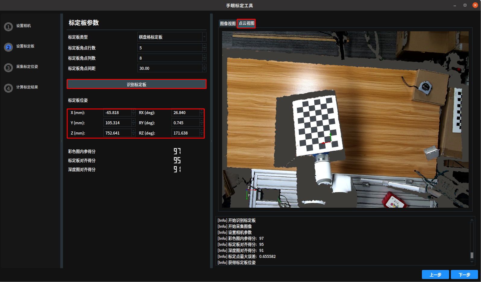
Get Calibration Board Pose
Click
Nextto enter theCapture Calibration Posesinterface. Click theGet Calibration Board Posebutton.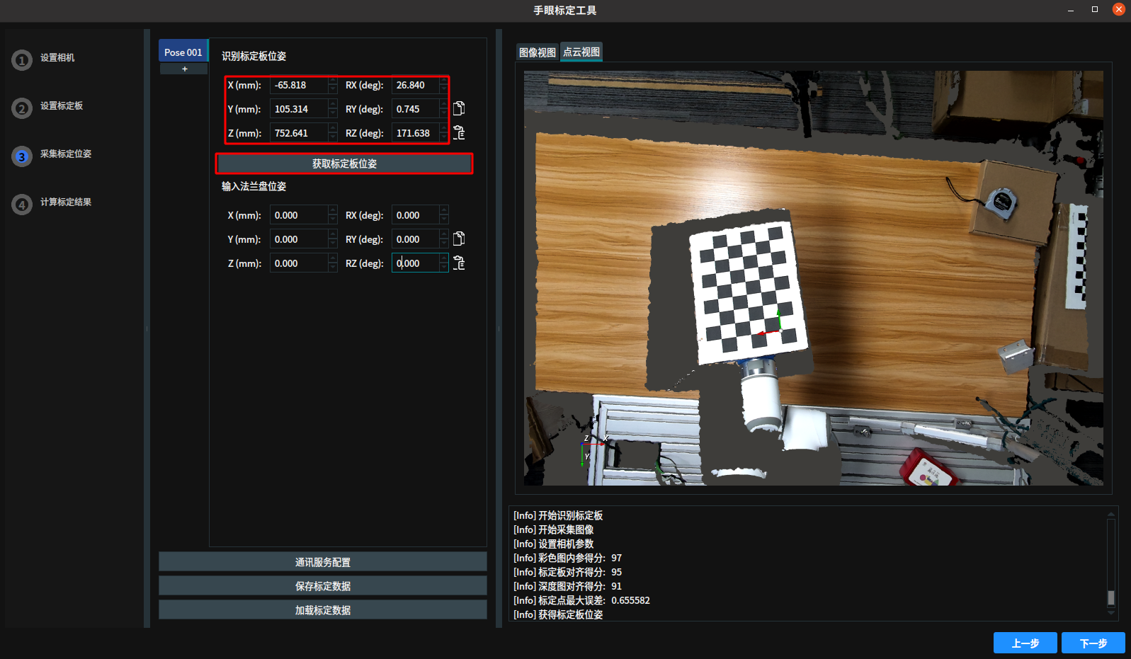
Get Flange Pose
Click
Communication Service Configuration, configure thePort NumberandSeparator. ClickStartto start the communication service.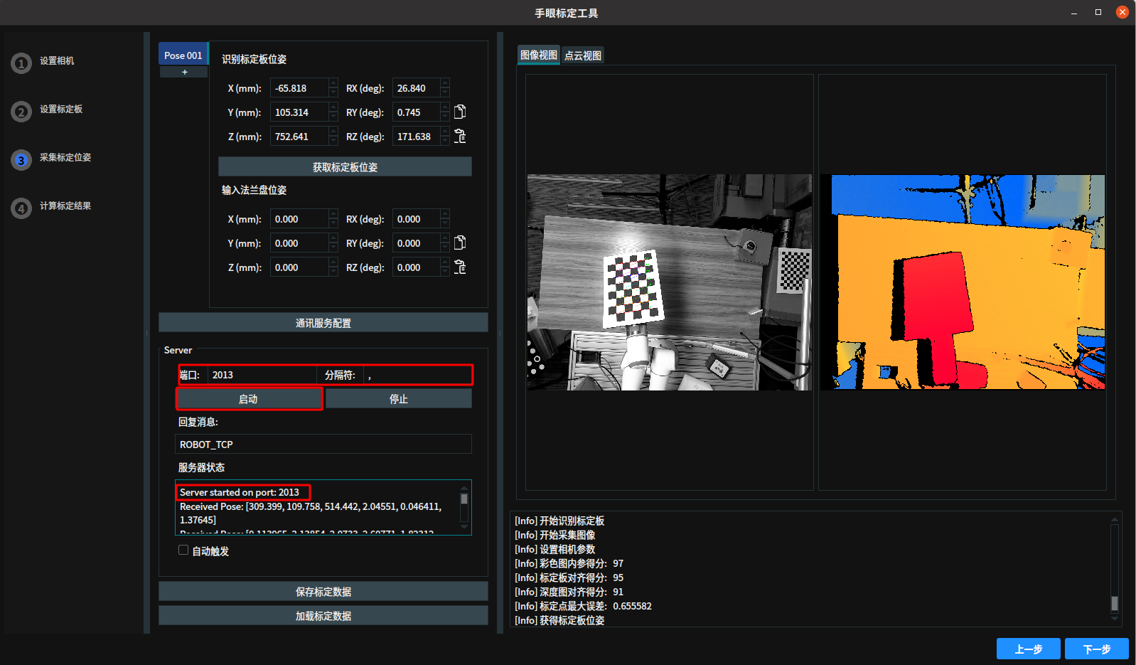
Control the robot to send ROBOT_TCP to RVS (requires assistance from a robot engineer). After RVS receives it, the current flange pose is displayed in the
Input Flange Pose.Note
The flange pose received by RVS is in millimeters and degrees.
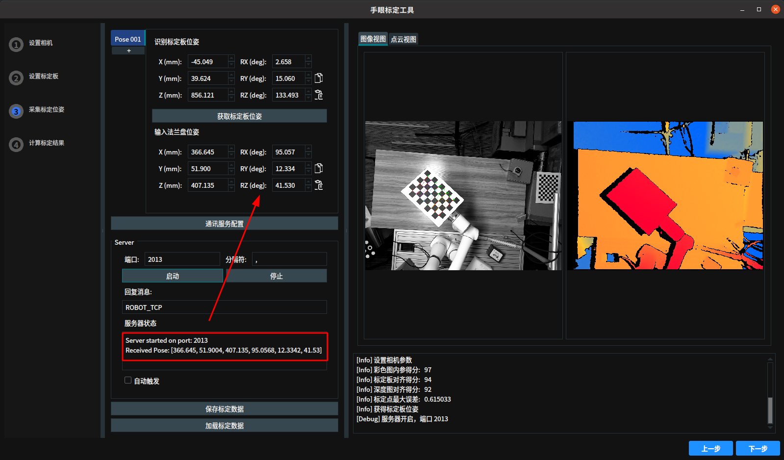
Click
+to save the next set of calibration data, or clickAuto Triggerto automatically switch to the next set.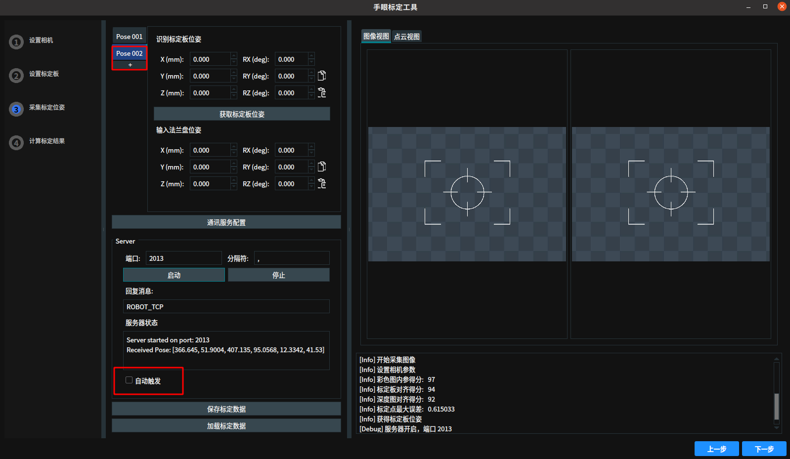
Move the chessboard within the camera’s field of view to ensure coverage of different positions and angles. Repeat the
Get Calibration Board PoseandGet Robot Flange Posesteps to collect 18 to 25 sets of calibration data. If the data is incorrect, right-clickPose XXXto delete it.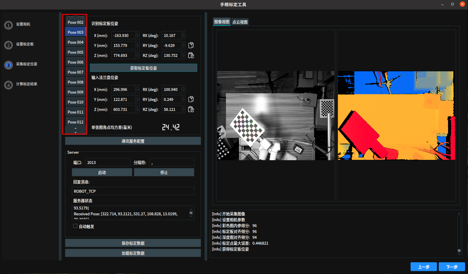
Click
Save Calibration Datato save the calibration data to the specified folder.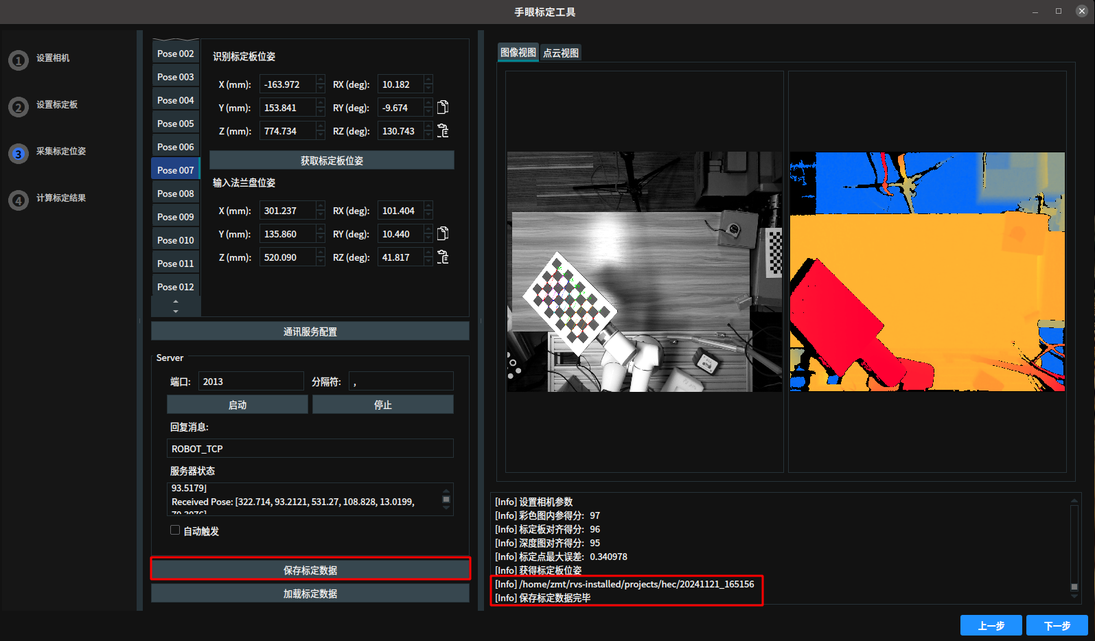
Calculate Calibration Results
Click
Nextto enter theCalculate Calibration Resultsinterface. ClickCalculate Calibration Resultsto perform the calibration calculation. After the calculation is complete, the calibration full corner RMSE is displayed. The calibration results can be copied for subsequent use by clicking theCopybutton.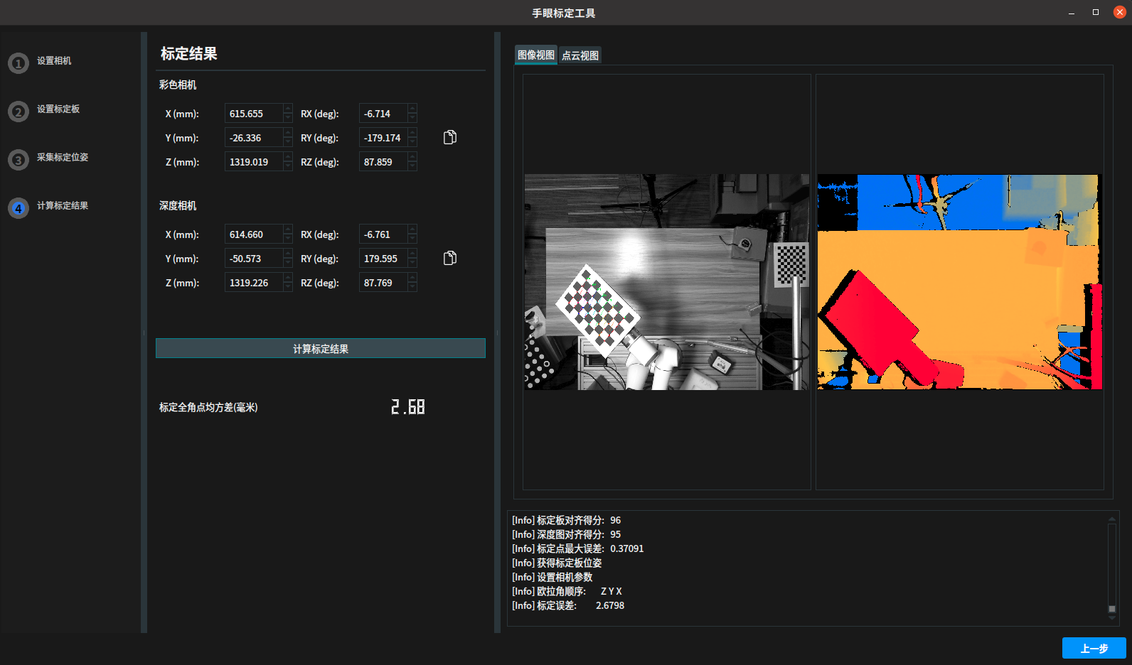
Tyto Ring Calibration Board Hand-Eye Calibration
The process of using the Tyto Ring Calibration Board for hand-eye calibration is basically the same as using the chessboard. Below is a brief description of the Tyto Ring Calibration Board calibration process. For detailed steps, refer to Chessboard Hand-Eye Calibration:
Camera Parameters: Set the corresponding camera and calibration parameters to ensure RVS can correctly identify the calibration board.
Calibration Board Parameters: Select the appropriate calibration board size (e.g., RCCB-28, RCCB-54, etc.) based on requirements.
Capture Calibration Poses: Move the calibration board within the camera’s field of view to ensure coverage of different positions and angles. Obtain the calibration board and robot flange poses, and collect 18 to 25 sets of data.
Data Verification: Check the validity of the calibration data to ensure the color image intrinsic score, calibration alignment score, and depth image alignment score are all above 90.
Calculate Calibration Results: Use the collected data to perform hand-eye calibration.
Ensure the stability of the calibration board throughout the process to improve the reliability of the calibration results.
Hand-Eye Calibration Error Analysis
Different robots paired with different camera types may exhibit different accuracy levels. If the calibration results are not ideal, refer to the following sections for troubleshooting.
Hardware Issues
Inaccurate calibration board parameter input.
Camera resolution does not match the calibration parameter resolution.
The calibration board is damaged or dirty.
The calibration board’s corners are not clearly captured; avoid overexposure or underexposure.
Calibration board size recommendation: It should occupy 1/3 to 2/3 of the camera’s field of view.
Data Issues
Saved data is disordered, meaning the capture position and saved TCP do not correspond.
Data units are not synchronized with RVS.
Confirm the Euler angle order: Non-fixed axis is Z-Y-X, fixed axis is X-Y-Z. RVS uses non-fixed axis.
Confirm the communication units: RVS defaults to mm for length and deg for angles.
Confirm the sent coordinate format is correct: RVS supports the format [x y z Rx Ry Rz].
Operational Issues
The robot pose changes are too small.
The robot arm is not stable after changing poses before data collection.