Knowledge Base
RVS software involves some important concepts and terms. Here are some explanations:
Node:An important concept in RVS that corresponds to a specific task or function. For example, the Load node can load elements such as Cube, Image, PointCloud, and so on. The Emit node can generate Cube, Line, Circle and other elements. Operators can integrate and process tasks by connecting with each other.Group:In RVS, multiple nodes can be encapsulated into a Group to improve the reusability and maintainability of nodes.XML:The XML file is an important configuration file in RVS. It contains the structure information of the whole project, input and output information of the node, interface configuration and so on. When using RVS to develop a project, it is necessary to write and save the corresponding XML file according to the actual requirements.Resource:Used for hardware devices or virtual devices to interact with RVS. If you need to connect the camera, add the TyCameraResource resource node. After the connection is successful, you can perform operations such as image collection and click capture.In short, RVS is an node based 3D machine vision development platform, which realizes the organization, management and visualization of algorithm flow through the standardized management of XML configuration files and resources.
Node Browser
2D:For 2D image processing.
3D:For 3D image processing.
Basic:Base node. Such as loading elements, saving elements, traversing elements, and so on.
Box Unstack:Used for unstacking.
Calibration:For different forms of calibration algorithm.
Communication:For communication with different robots, industrial computer.
File:For system file management.
Geometry Detection:For cylinder and plane detection and filtering.
ICP:For icp algorithm template matching.
Motion Planning:For robot arm motion planning.
Python:For AI training and detecting, secondary development in python.
Robot:Used to control the simulation of the robot movement behavior as well as the main model generation.
Surface:For data processing in polydata.
Tycamera:Used to control and manage the Percipio camera and SDK.
Universal Robots:For the active control of UR robot.
Resource:For hardware devices (including virtual devices) to interact with RVS.
Each node can be in node introduced queries.
Control Signal
Node orange ▶ is the control signal port, the control signal port does not distinguish type categories, can be connected to each other.
| ▶ Port name | Feature |
|---|---|
| start | Trigger node. |
| finished | When the node is triggered and runs successfully, the finished port of the node sends a trigger signal, and when the finished port is connected to the next node, the next node is triggered. |
| failed | The node has been triggered, and the operation has completed, but the expected output result is not obtained, then the failed port of the node will give a trigger signal. |
| stop | Pause the node. |
| reset | Reset node. |
| iterate | Run iteratively. |
| started | If the start port on the left is triggered, the started signal on the right is triggered. |
| processing | / |
| stopped | This port is triggered when the stop port is triggered. |
| reset | This port is triggered when the reset port is triggered. |
| iterated | This port is triggered when the iterate port is triggered. |
Data Signal
Sky blue ● ■ is the data signal port,● is a single data,■ is list data.Data ports differ by data type,Commonly used ports include cloud, image, string, pose, cube, and their corresponding list data such as cloud_list, image_list, etc.Only data ports of the same type can be connected to each other.
Only data ports of the same type can be connected to each other.
| Data type | ●■ Port name |
|---|---|
| Image/ImageList | image/image_list |
| ImagePoints/ImagePointList | image_points/image_points_list |
| Pose/PoseList | pose/pose_list |
| JointArray/JointArrayList | joint/joint_list |
| Cube/CubeList | cube/cube_list |
| Sphere/SphereList | sphere/sphere_list |
| Angle/AngleList | angle/angle_list |
| Circle/CircleList | circle/circle_list |
| Line/LineList | line/line_list |
| Path/PathList | path/path_list |
| PointCloud/PointCloudList | cloud/cloud_list |
| Cylinder/CylinderList | cylinder/cylinder_list |
| String/StringList | string/string_list |
| PolyData/PolyDataList | polydata/polydata_list |
| Object/ObjectList | object/object_list |
| Text/TextList | text/text_list |
| CameraInfo | camera_info |
| CalibInfo | calib_info |
| RobotInfo | robot_info |
| RotatedRect | rect/rect_list |
| MotionPlan | motion |
| PlannedGrasp | grasp/grasp_list |
Coordinate System Explanation
The RVS software has a built-in 3D view environment, which is the world coordinate system BaseXYZ with the origin at (0,0,0). Poses generated by operators like Emit-Pose are all based on the BaseXYZ coordinate system.
The simulated robot is defined by a CAD model file and has its own base coordinate system RobotXYZ. Since the CAD model of the robot is aligned with the world coordinate system when created, when importing the CAD model file into the RVS software, the RobotXYZ coordinate system is automatically aligned with the BaseXYZ coordinate system.
The 3D point cloud generated by the Graphon camera also has its own coordinate system, the left IR coordinate system CameraXYZ. When displaying CameraXYZ in the BaseXYZ coordinate system, the camera’s left IR is initially positioned with a pose of (0,0,0,0,0,0). However, this display has no practical meaning. We need to find the true spatial pose of the camera in the robot coordinate system, and then correct the CameraXYZ coordinate system in the BaseXYZ coordinate system according to that pose.
In addition, the target captured by the camera, such as a box, also has its own object coordinate system ObjXYZ. This coordinate system represents the pose of the target object.
In the RVS software, each pose (x, y, z, rx, ry, rz) represents a spatial pose and is also represented by a 4x4 coordinate transformation matrix.
This pose includes translation and rotation information:
(x, y, z) represents the translation vector of the matrix, i.e., the position of the object in 3D space.
(rx, ry, rz) represents the rotation vector of the matrix, i.e., the rotation angles of the object relative to the reference coordinate system.
Euler Angle Introduction
In three-dimensional space, the rotation of a coordinate system around the origin has three degrees of freedom, requiring three independent rotation parameters to describe. Euler angles are a commonly used representation for describing rotations and were first introduced by Euler.
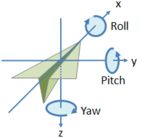
They consist of three angles, known as roll, pitch, and yaw.

Compared to the direction cosine matrix and quaternion representations, the Euler angle representation has the following advantages: it requires the fewest parameters, only three angles; it has a more intuitive physical interpretation and is easier to understand.
The rotation in Euler angles is performed using a non-fixed axis rotation, meaning that the rotation axis changes as the rotation progresses. The definition of Euler angles is not unique, and there are multiple ways to define them depending on the order of rotations around the coordinate axes.
Euler angles can be divided into two main categories: classical Euler angles and Tait-Bryan angles. Among them, Tait-Bryan angles are more commonly used. These two types of Euler angles can be further divided into the following 12 sequences based on the order of rotations:
Classical Euler angles: Z-X-Z, Z-Y-Z, X-Y-X, X-Z-X, Y-X-Y, Y-Z-Y
Tait-Bryan angles: X-Y-Z, X-Z-Y, Y-X-Z, Y-Z-X, Z-X-Y, Z-Y-X
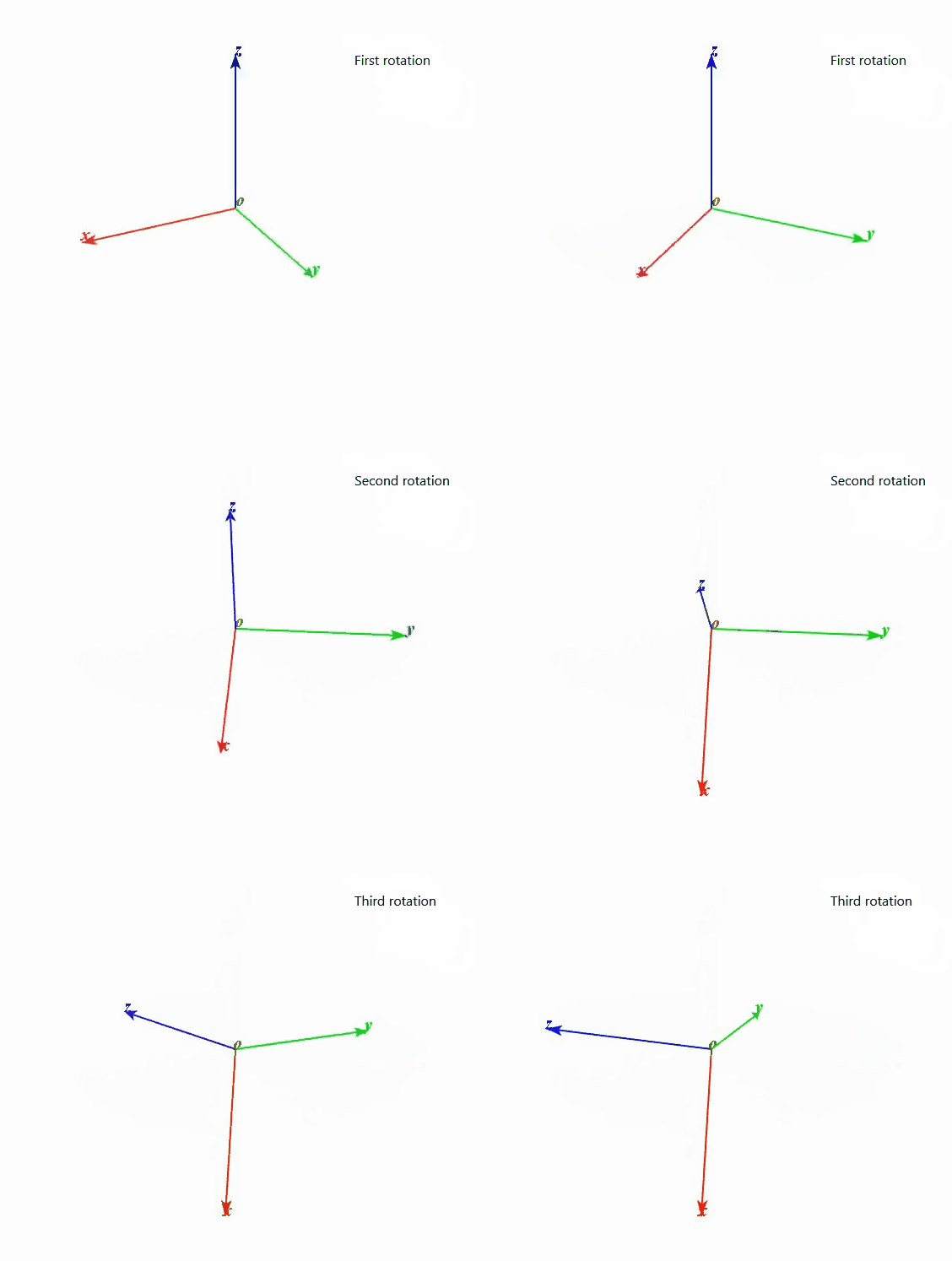
In RVS, the rotation angles of the pose are defined using the Z-Y-X order, which means rotating around the Z-axis (yaw) first, then rotating around the rotated Y-axis (pitch), and finally rotating around the rotated X-axis (roll).
This rotation follows the right-hand coordinate system rule, and the rotation angles are measured in radians.
The rotation sequence of the pose in RVS is illustrated in the following diagram:
