When you obtain this document, Available for download from the RVS developer community FourAxisCalibration.zip four-axis robot calibration tutorial supporting data. After decompression, its contents should include:
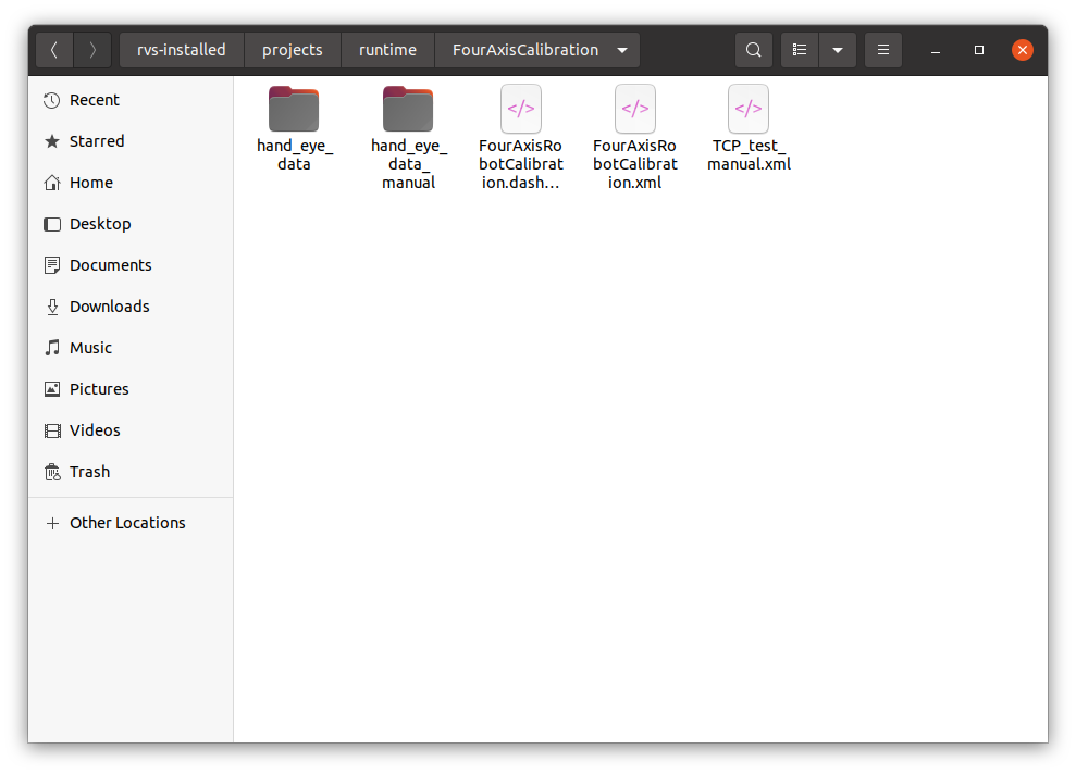
TCP_test_manual.xml:For communication testing.FourAxisRobotCalibration.xml:For hand-eye calibration data recording, matrix calculation, calibration results verification.hand_eye_data_manual:A case of standard data recording in hand-eye calibration.hand_eye_date:Empty directory, the directory where data is saved and read during hand-eye calibration.
All files used in the case are saved under FourAxisCalibration.zip and run under projects/runtime in the RVS installation directory.
Note
The version of RVS software used in this document is 1.5.468. If there is any problem or version incompatibility in use, please contact us at rvs-support@percipio.xyz!
Four-axis robot hand-eye calibration
Introduction to hand-eye calibration
Hand-eye calibration refers to solving the conversion matrix from camera coordinate system to robot coordinate system according to the coordinates of points in robot coordinate system and camera coordinate system after camera installation. The purpose is to convert the point cloud taken in the camera coordinate system to the robot coordinate system according to this coordinate transformation matrix.
Four-axis robot hand-eye calibration:
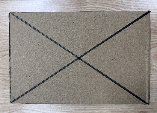
mode:HandToEye,The camera (ceiling) is fixed and relatively fixed to the robot base coordinate system.grasp object:Objects such as cardboard boxes or wooden blocks can be used to easily identify and locate the geometric features of the object (such as the center point of the upper surface of the wooden block).Suggestion
The feature points of the object are marked to facilitate the end calibration of the robot tool and the point cloud identification of the judging camera.
As shown in the picture below:
The hand-eye calibration process is divided into the following steps:
Communication test:Ensure that the RVS software can start normally and establish communication with the robot to prepare for the next data recording.
Connect the camera:Make sure the camera is connected properly in the RVS software.
Save data:Save the pose of multiple groups of grasping points in the robot coordinate system and the pose of the camera coordinate system.
Calculate calibration:Calculate the calibration result.
Verify calibration result:The calibration results are used to move the robot to verify whether the calibration is accurate.
Communication test
The purpose of the communication test is to ensure that the RVS software can start properly and establish a normal communication with the robot in preparation for the next data recording.Used in this manual HandEyeTCPServer, Start a TCP server server in the RVS thread and wait for the robot to establish a connection and perform tcp communication.
Operation process :
Note
Communication tests can be performed directly using TCP_test_manual.xml under the FourAxisRobotCalibration/ path, or you can create TCP_test.xml yourself by following these steps.
Step 1: Create TCP_test.xml
Create a new project and rename it TCP_test.xml.
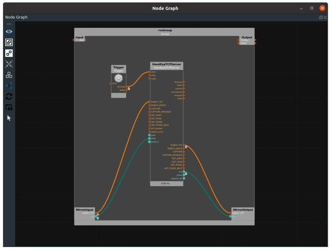
TriggerandHandEyeTCPServernodes in the node graph.Add nodes and form a Group. Drag
TriggerandHandEyeTCPServernodes into the node graph to synthesize the two nodes into a Group.Set the node parameters.
Trigger:type → InitTriggerHandEyeTCPServer:No parameters need to be modified for local testing.Set this parameter based on the actual scenario.For details, seeHandEyeTCPServer。
Engineering connection.
The ROBOT_TCP on the right of
HandEyeTCPServernode is connected to MirrorOutput, and then the corresponding term on the left ofHandEyeTCPServernode is connected from MirrorInput.A loop is formed so that information can be returned to the client when the instruction is received. The node graph is connected as follows.
Step 2: Perform the local HandEyeTCPServer Communication test
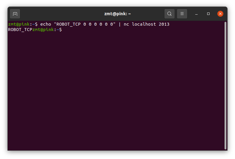
After the project is started, you can test it locally by opening the terminal and typing:
echo "ROBOT_TCP 0 0 0 0 0 0" | nc localhost 2013
If it runs successfully, ROBOT_TCP is returned separately in the terminal, as shown in the figure below:
The following figure is displayed in the RVS log view:

Step 3: Conduct communication test between RVS and robot terminal
Robot Engineer assistance :
The robot gets the current TCP value and sends the following string, x y z in meters, rx ry rz in radians, to the RVS server through the connection. The rx ry of the four-axis robot should be fixed.
ROBOT_TCP x y z rx ry rz \n
After success, the robot should establish normal communication with the RVS.
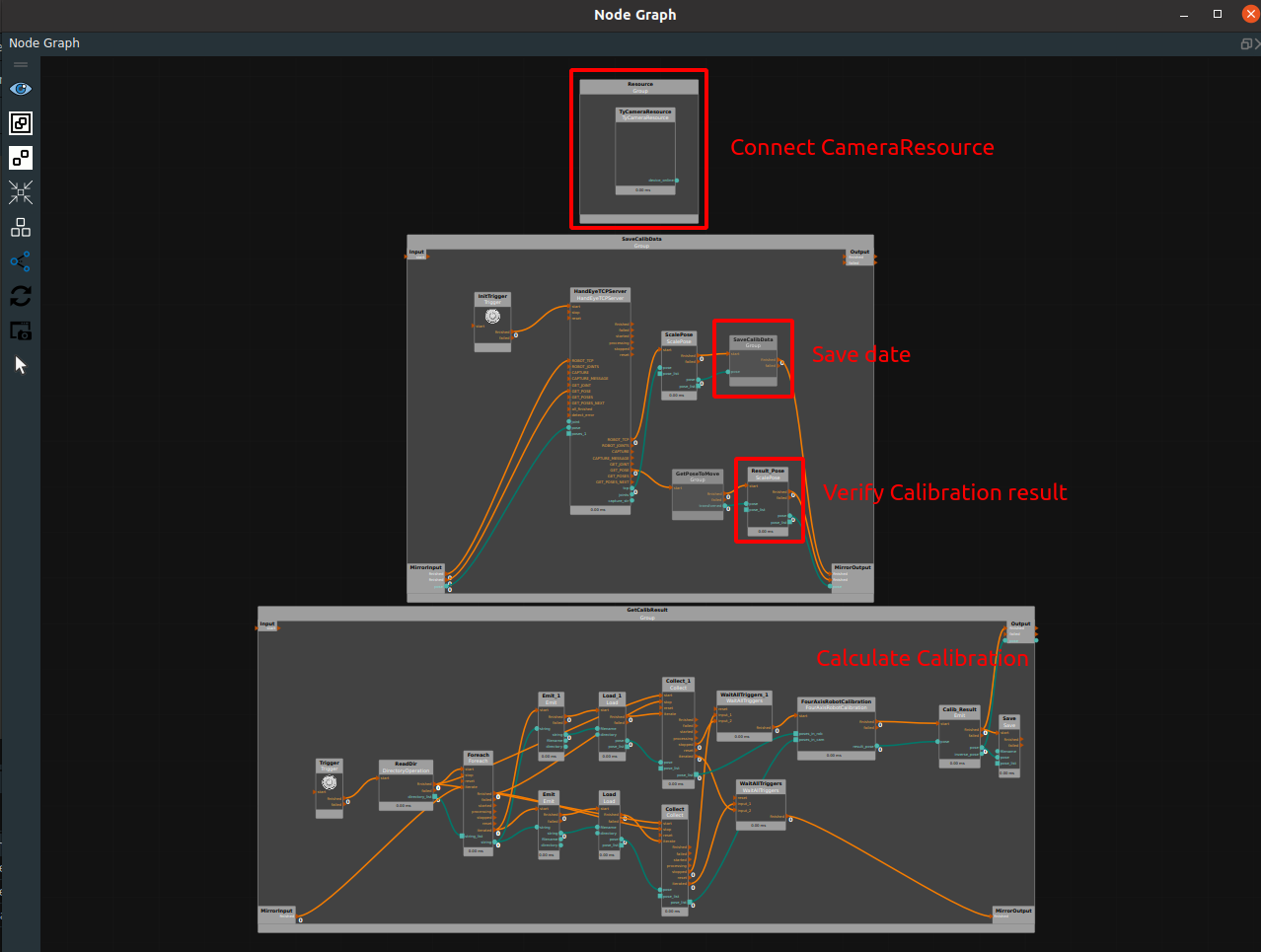
When RVS has established communication with the robot, the data recording session will officially begin. A standardized four-axis robot hand-eye calibration module is provided in RVS. Please open the FourAxisRobotCalibration/FourAxisRobotCalibration. xml
In this xml, the whole is divided into connecting camera resources, storing data, calculating calibration results, and verifying calibration results.
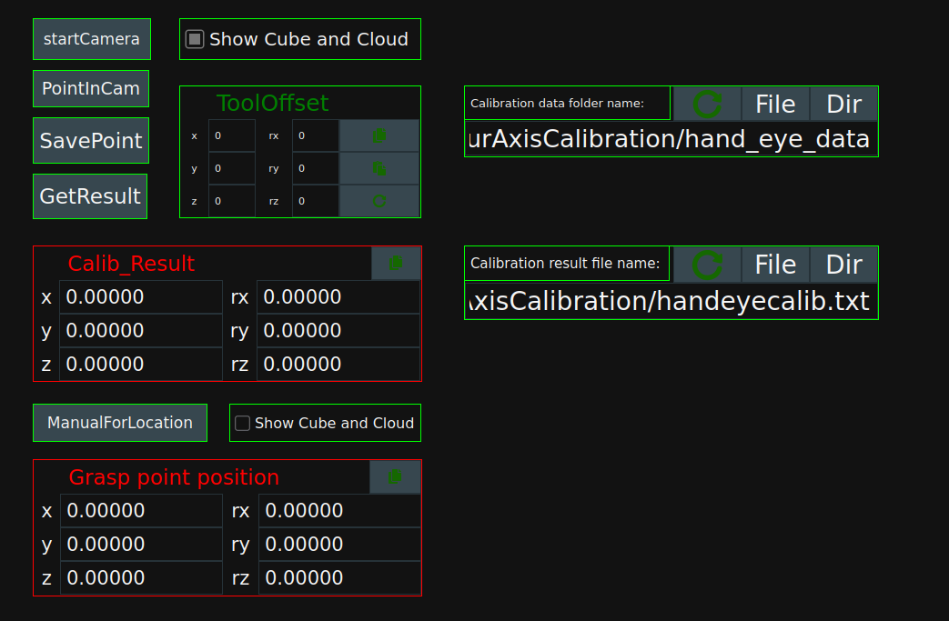
The dashboard contains the following controls, which are explained in detail during the calibration process:
Connect the camera
Open RVS software,Loading FourAxisRobotCalibration/FourAxisRobotCalibration. xml project files.
After running the project, click
startCamerain the dashboard to connect the camera.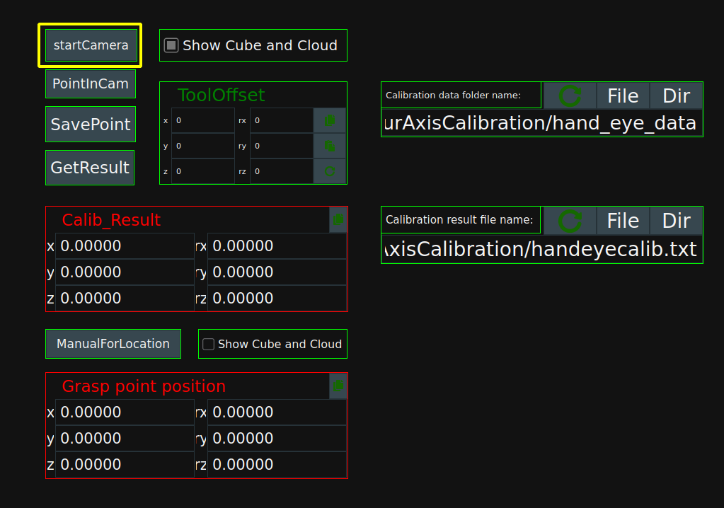
Note
If the camera connection fails, see What if the RVS cannot connect to the camera?
After the camera is successfully connected, the following log message is displayed indicating that the camera is successfully connected. The
TyCameraResourcenode is displayed in blue.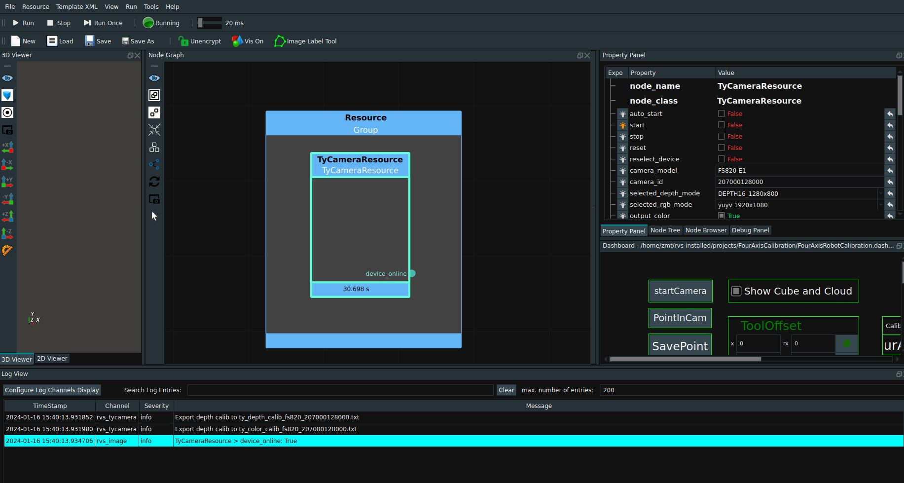
Save data
According to the pose of the grasping point in the robot coordinate system and the pose in the camera coordinate system, the transformation matrix from the camera coordinate system to the robot coordinate system is solved during hand-eye calibration of the four-axis robot.In theory, at least 4 sets of nonlinearly related pose points are required to calculate a 4*4 coordinate transition matrix.In general, 6~8 groups of grasp points are saved in the pose of robot coordinate system and camera coordinate system, named PoIntiCam.txt and PointInRob.txt are saved in hand_eye_data folder, and each group is saved in the form of time stamp.
Note
It is necessary to first obtain the pose of the grasping point in the robot coordinate system, and then obtain the pose of the grasping point in the camera coordinate system, so as to avoid the offset of the grasping object when the grasping point is calibrated by the end of the robot tool, resulting in errors in the pose of the grasping point in the camera coordinate system.
Pose of grasp point in robot coordinate system
The end of the robot is moved to the grasp point of the object manually, and the robot sends the current TCP pose to the RVS through the communication script.
Send format:ROBOT_TCP X Y Z 0 0 0#
Note
If the robot does not establish tool tcp, the tcp here is the default flange tcp of the robot. In this case, the value of ToolOffset needs to be set according to the actual tool, so that the saved data is the end pose of the tool that has been calibrated with the grasp point, rather than the end pose of the flange.
If the robot has established tool tcp, skip step 2 below.
In the dashboard
ToolOffsetsets the ToolOffset according to the actual tool.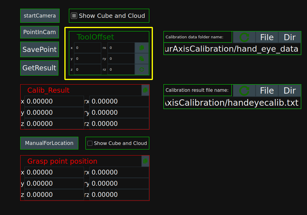
The grasping point from the end of the robot to the object is shown in the figure below:

The pose units used in RVS are all meters and radians. If the TCP pose sent by the robot is millimeters and angles or other units, the unit of pose point needs to be converted by
ScalePosenode after the pose output by the TCP communication node. Similarly, the grasp point pose recognized by RVS, It can also be converted into the unit system needed by the robot side through theScalePosenode, and then sent to the robot through communication.If the
ScalePosenode is set to 1 if no conversion is required, the output value will not change numerically.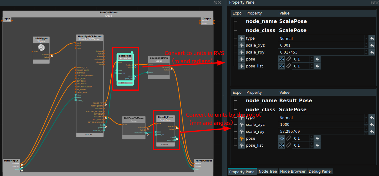
Note
After sending the current TCP pose to RVS, keep the grasp still and move the robot out of camera view.
Pose of the grasp point in camera coordinate system
Click
PointInCamin the dashboard, checkShow Cube and Cloud, double-click cube in the 3D view, set the scope of work.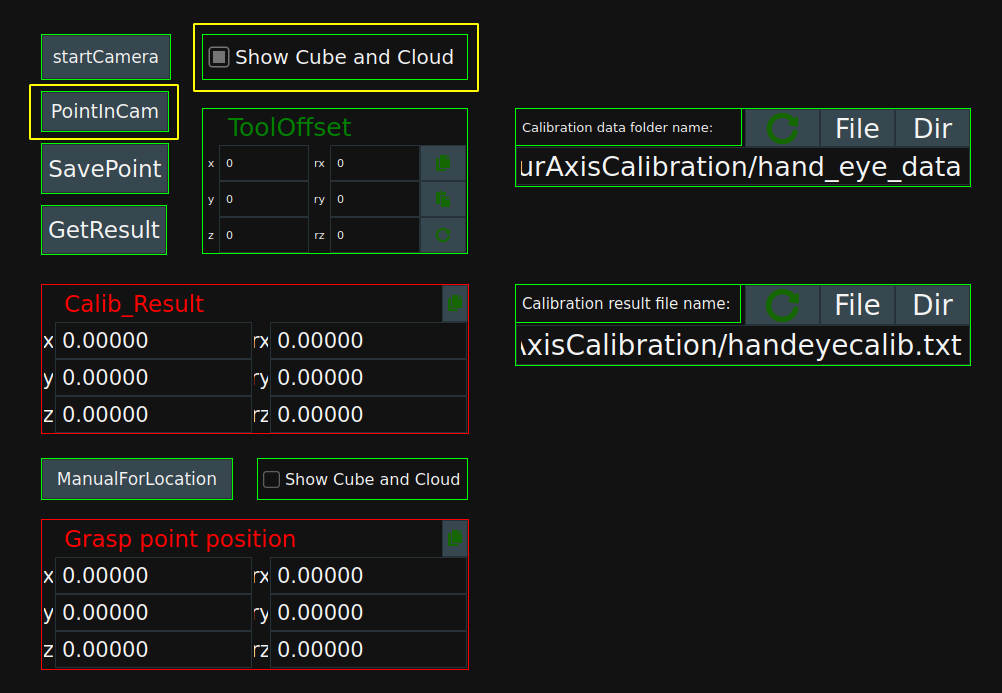
Working range requirements: the XY direction is consistent with the camera’s field of view, and the Z direction ensures that the surface of the grasp that needs to be extracted can be cut each time. As shown in the picture below:
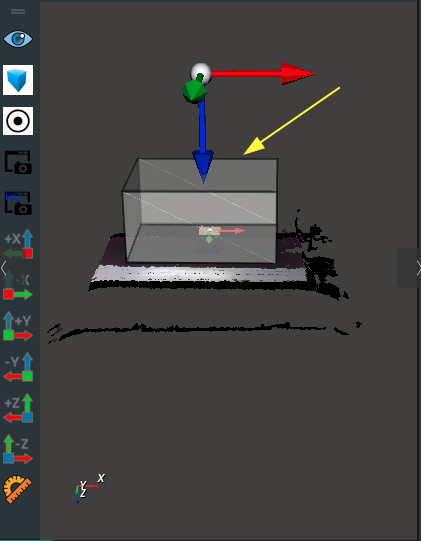
Click
PointInCamin the dashboard again to determine the grasp point of the positioned object.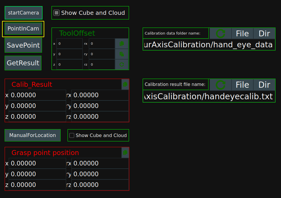
Save grasp point coordinates
When the pose of the grasping point is obtained in the robot coordinate system and the camera coordinate system, it is shown in the following figure respectively in RVS.

Click
SavePointin the dashboard to save the grasp point location in robot coordinate system and camera coordinate system and save it in the hand_eye_data folder under FourAxisCalibration directory as a timestamp.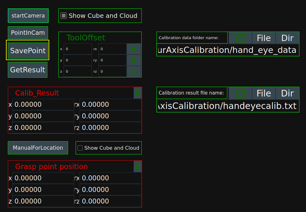
After a single group is successfully saved, the following figure is shown:
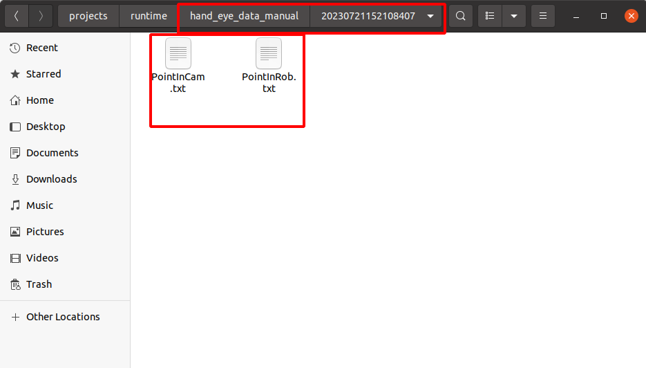
Notes
After each placement of the object is selected, the object is no longer moved during the operation of each group.
Repeat the above operations for 6 to 8 groups to ensure that the calibration results can be correctly calculated.
The poses of all captured points in any coordinate system must be linearly independent. For example :3 points are not in a straight line, 4 points are not in the same plane.
Calculate calibration
When we have finished recording the data, please double check that the data under the folder is complete and then start calculating the calibration result.
Operation process :
Still in FourAxisRobotCalibration/FourAxisRobotCalibration. xml project.
Check whether the read path is the same as the save path in the
Calibrate Data folder namein the dashboard.Click the
GetResultbutton on the dashboard to read the previously calibrated recorded data for calculation.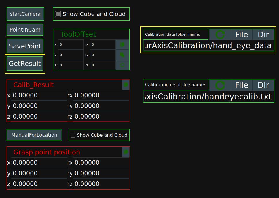
The error is shown in the log view window of the program, as shown below.

How to determine whether the error is normal?
Different robots with different camera types will have different precision performance. Generally speaking, positional error is less than 0.003 (3 mm), which is ideal. If the error is large, check that the preceding steps are performed correctly.
The calibration result is displayed in the form of pose in the
Calib_Resulttable of the dashboard. When the accuracy meets the fluctuation allowed within the error range, theCopybutton can be clicked to copy the calibration result. Calibration results at the same time saved to FourAxisCalibration/handeyecalib. txt file.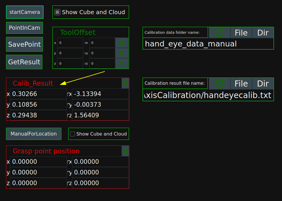
Verify calibration result
Click
GetPosein the dashboard, checkShow Cube and Cloud, double click cube in the view, and set the working range of the actual workpiece. The cube here is used to segment the point cloud under the robot coordinate system.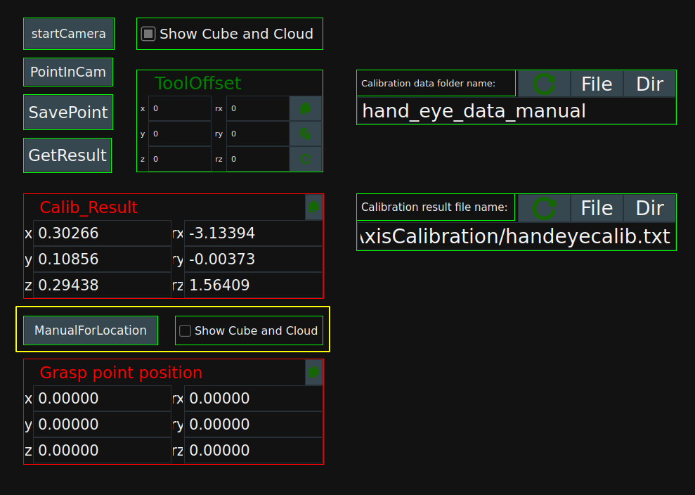
The grasping point in the robot coordinate system can be obtained in the following two ways.
Method 1: The robot sends GET_POSE, and RVS will reply the location of the grasp point to the robot.
Send format::GET_POSE #
Method 2: Click
ManualForLocationin the dashboard. The pose of the grasp point will be displayed in the dashboardgrasp point position, and the robot value can be manually moved to the grasp point. At this time, the grasp point pose in the RVS dashboard is compared with TCP in the robot remote control interface to verify whether the calibration is correct.
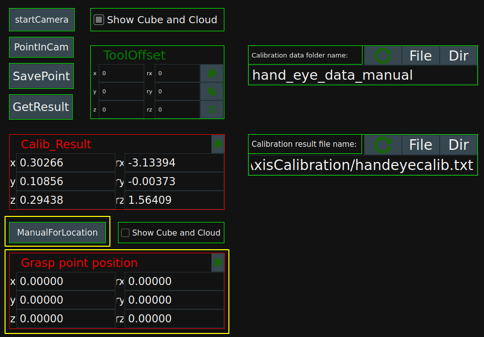
Verify 3~5 groups, if there is no problem, calibration is completed.