This document explains how to use RVS software to complete a template matching case. The case demonstrates the complete workflow from data preparation, template point cloud generation, target point cloud processing, to template matching and result verification.
Preparation for Template Matching
Data Preparation
Obtain Offline Data
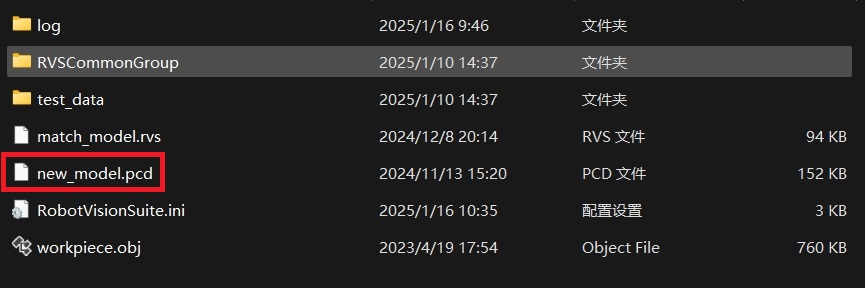
The RVS developer community provides 3D template matching offline projects and data to help users quickly get started, validate functionality, and save time. Click model_matching.zip to download. After extraction, the contents include:
File Description
| File | Description |
|---|---|
| RVSCommonGroup | This folder contains commonly used Group sets, which can be loaded as needed. |
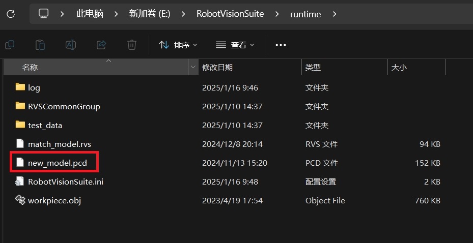
| new_model.pcd | This file is the completed template point cloud file. |
| match_model.rvs | Used for offline template matching. When using, update the path of offline data in the ReadDirectoryNames operator and the template point cloud file in the LoadModelCloud operator. When using, first click the start button in the interaction panel to start the project, then click the iterate button to iterate through the offline data in test_data. |
| test_data | This folder contains target point cloud files for loading template matching data. Please ensure the correct path is used. |
| workpiece.obj | The 3D model file used for loading in the Load-Polydata operator in create_model.xml. |
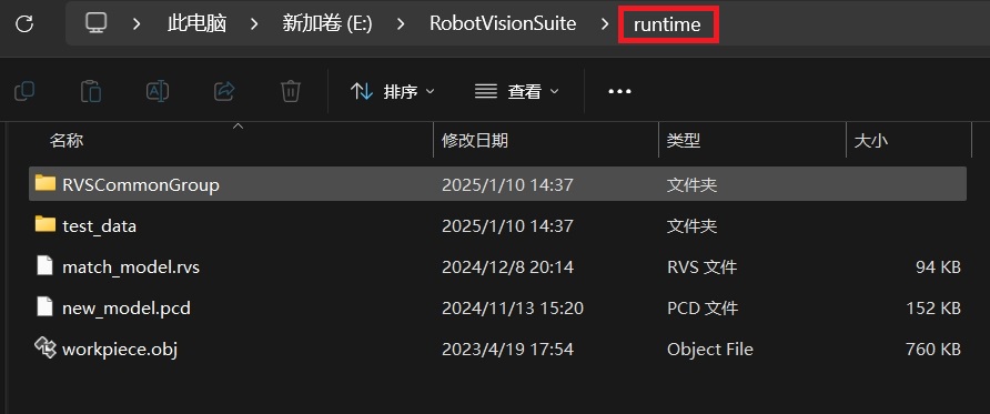
All files used in this case are saved in the model_matching folder. Please place it in the RVS installation directory to run.
Note
If using the Linux version, place the model_matching folder in the projects directory under the RVS installation directory.
If you do not want to adjust the file paths in the project, you can rename model_matching to runtime.
This document uses RVS software version 1.8.321. If you encounter any issues or version incompatibility, please provide feedback promptly by sending an email to rvs-support@percipio.xyz!
Custom Data
If you want to use custom data for template matching, prepare the following data files.
| Preparation File | Description |
|---|---|
| 3D Model File | Used to generate the template point cloud. RVS supports model file formats: .ply, .stl, .obj, .gltf, *.glb. If the current model file format is incompatible, conversion is required in advance. |
| Target Point Cloud File | Used for matching result verification, including point cloud and color images. |
Template Point Cloud Generation and Processing
This section explains how to use the Create Point Cloud Template tool to generate and process the template point cloud of a 3D model, including the following steps:
Mesh Sampling: Create a point cloud from the given 3D model.
Process the template point cloud:
Mesh Sampling
Load the 3D model file and use the Mesh Sampling tool in Create Point Cloud Template to convert it into a point cloud.
Steps
Click the menu bar icon
 to open the
 Create Point Cloud Templateinterface, then click the icon to enter the mesh sampling settings interface.
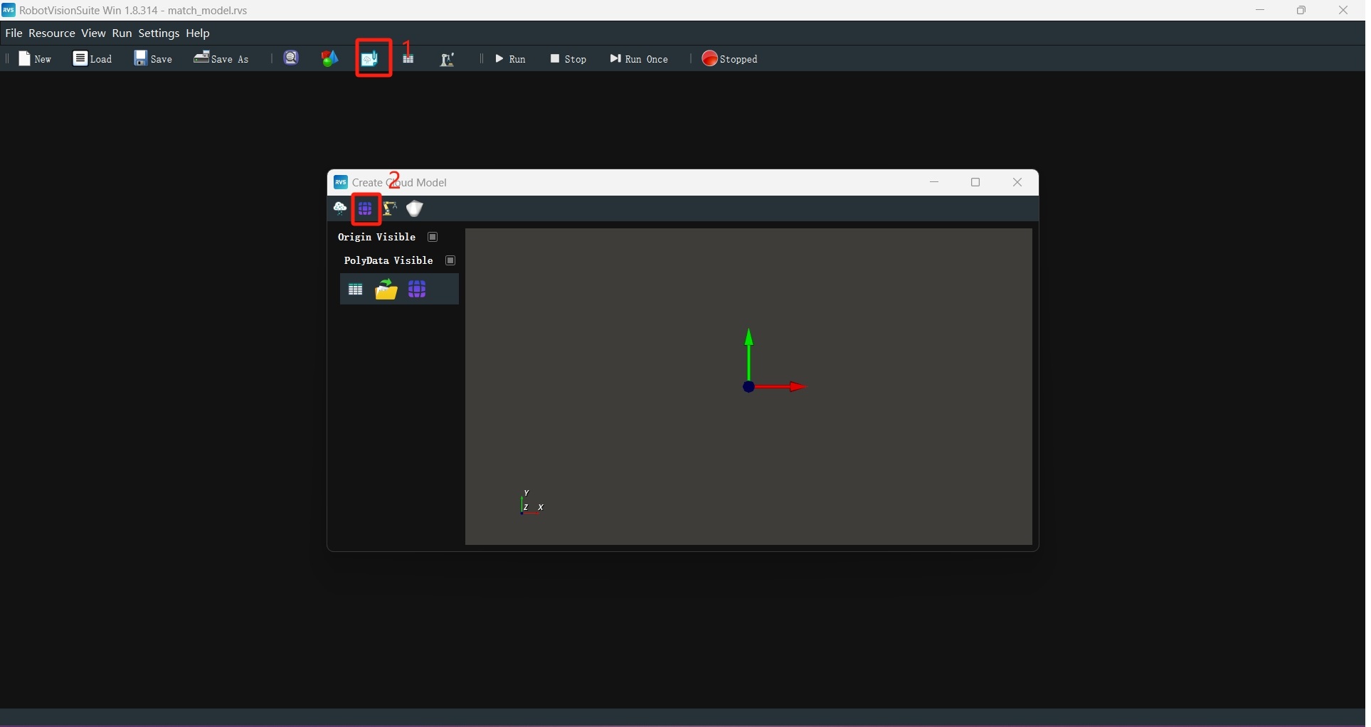
Click the
 icon to load the 3D model file. When using offline data, you can directly load the workpiece.obj file.
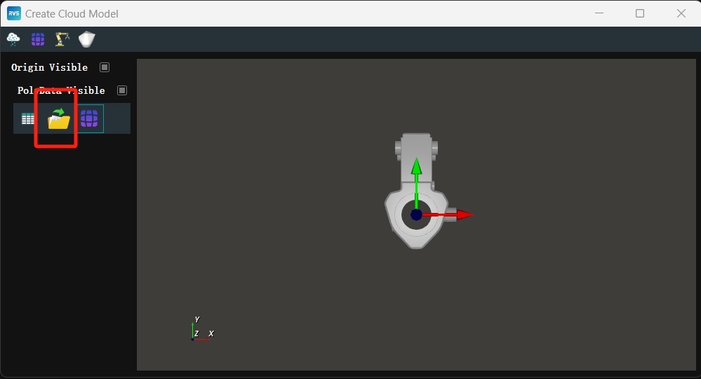
Click
 to open the
 Parameter Table Paneland adjust the parameters:leaf_size → 1
sample_points → 30000
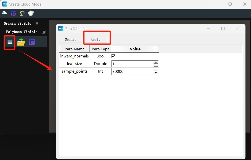
Click the
icon to complete mesh sampling.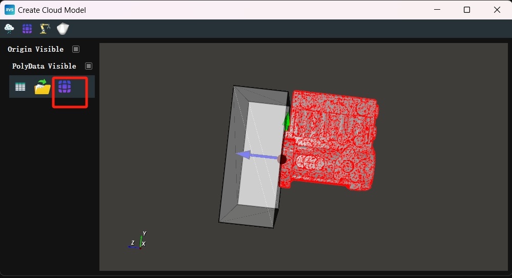
Cutting the Template Point Cloud
According to the requirements of the template matching task, cut the point cloud to retain only the upper surface of the model point cloud as the working area.
Steps
Click
 to enter the point cloud modification interface.
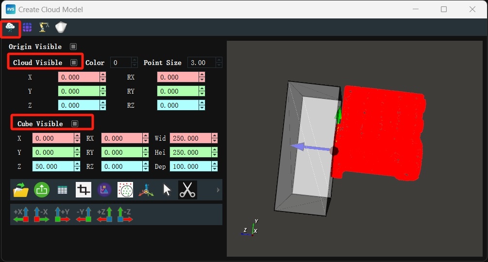
Enclose the required point cloud with a cube. Click the cube with the mouse to display the rotation axis, drag to rotate and move to the designated area, or fill in the parameters on the left to move and rotate the cube.
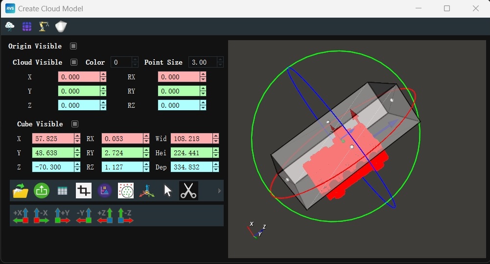
Click the
 icon to crop. After cropping, the result is displayed in the view.
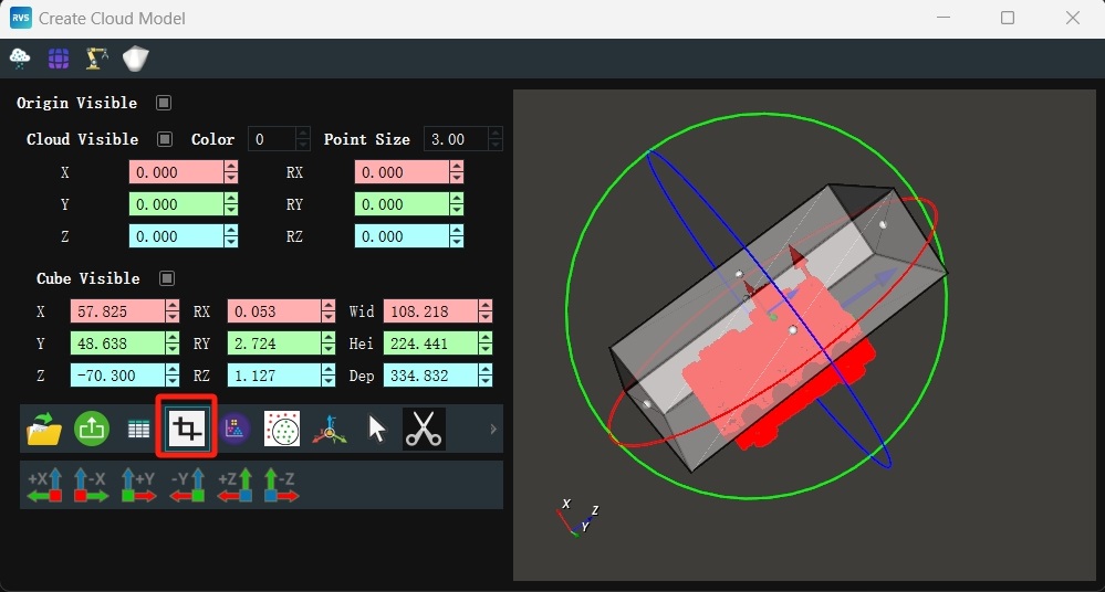
Adjusting and Saving the Point Cloud
To meet the requirements of the Match3D template matching operator, align the Oxy plane of the template point cloud with the Oxy plane of the actual incoming object point cloud and place the center of the template point cloud at the origin of the RVS 3D world coordinate system.
Note
Since the actual incoming object point cloud is located in the robot coordinate system, and the robot coordinate system coincides with the RVS 3D world coordinate system, transforming the template point cloud so that its Oxy plane is parallel to the RVS 3D world coordinate system’s Oxy plane and its center is at the origin of the RVS 3D world coordinate system will satisfy the input requirements of the Match3D operator.
Steps
Click
 to move the center of the template point cloud to the origin of the RVS 3D world coordinate system.
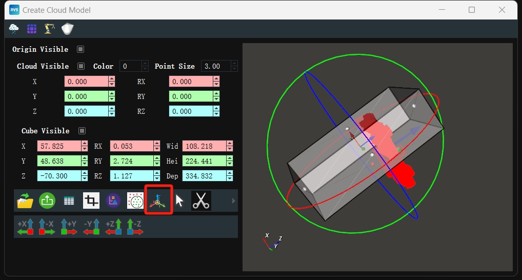
Set the point cloud RY value to
180to rotate the template point cloud 180° around the Y-axis, aligning the Oxy plane of the template point cloud with the Oxy plane of the actual incoming object point cloud.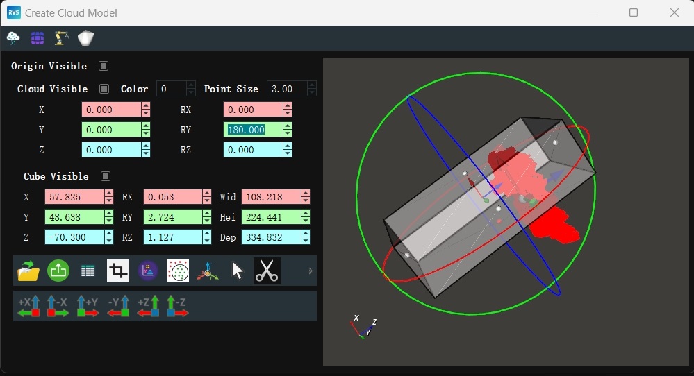
Click
 to export the prepared template point cloud, enter the file name, and click
 Save.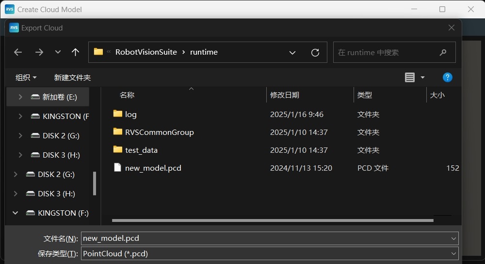
Check the saved “new_model.pcd” file in the runtime directory.
Point Cloud Downsampling
Load the new_model.pcd template point cloud file and perform further downsampling to improve operator execution efficiency.
Steps
Note
You can directly use the match_model.rvs under the model_matching/ path for template matching. Alternatively, you can follow the steps below to connect manually.
Create a new engineering project named “match_model.rvs”. (You can directly import the “LoadModelCloud.group” from the “model_matching/RVSCommonGroup” directory, paying attention to the file path.)
Create a new Group in the operator diagram. Add Trigger, Load, Emit, and DownSampling operators.
Tip
For methods on creating Groups and adding operators, refer to: Group Usage Guide and Node Usage Guide.
Set node parameters.
Set Group parameters: node_name → LoadModelCloud
Set Trigger node parameters: type → InitTrigger
Note
Used to automatically trigger the LoadModelCloud operator and the Emit operator.
Set Load node parameters:
node_name → LoadModelCloud
type → PointCloud
file → new_model.pcd (file path of the saved new_model.pcd, note the file path)
Cloud →
 Visible →
  90
90
Set Emit node parameters:
type → Pose
pose → 0 0 0 0 0 0
pose →
Visible
Note
Generates a pose based on the RVS 3D world coordinate origin (0,0,0,0,0,0).
Set DownSampling node parameters:
node_name → DownSampling_model
type → Downsampling
leaf_x → 2
leaf_y → 2
leaf_z → 2
Note
Indicates that only one point is taken within a spatial scale of 2mm * 2mm * 2mm.
Connection node.
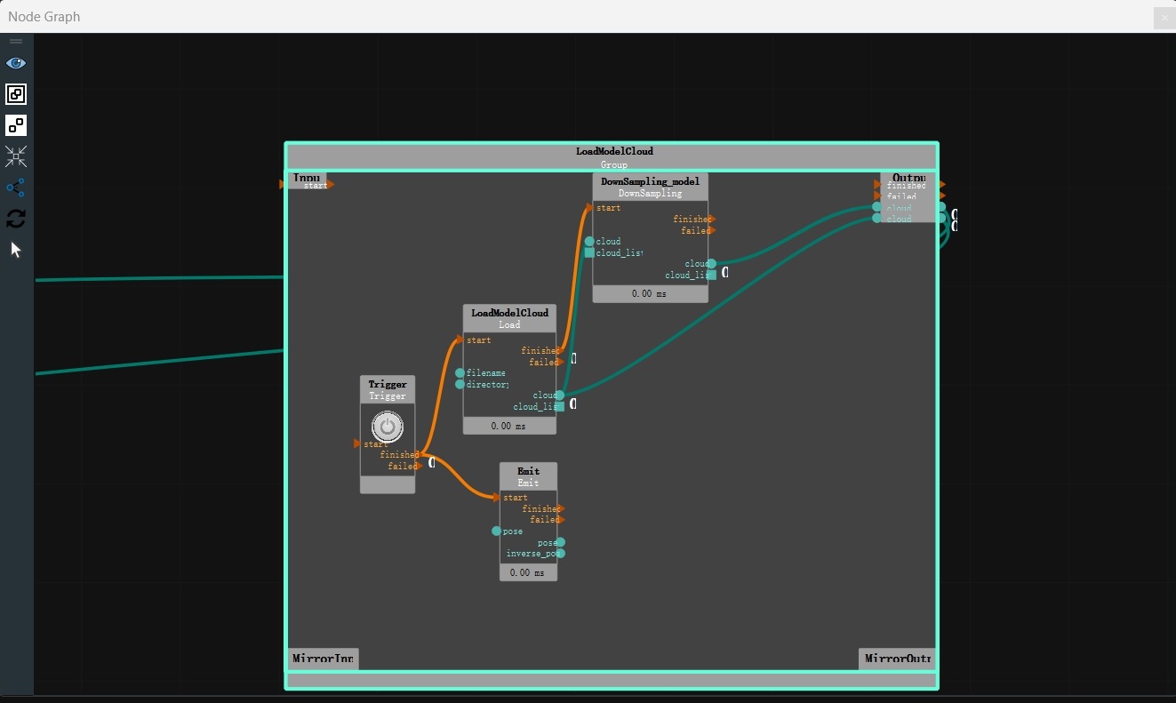
Click the RVS run button.
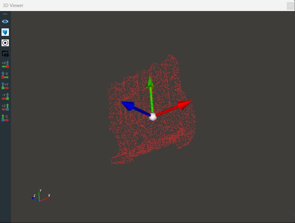
Run Result
As shown below, the loaded template point cloud and the generated origin pose are displayed in the 3D view. At this point, the origin pose is also the center point of the point cloud.
Target Point Cloud Preparation and Processing
Target Point Cloud Preparation
Load the target point cloud file. The test_data folder contains multiple sets of offline data, so the Foreach-String operator is used to traverse and load the target point cloud files.
Steps
Add Trigger (2 instances).
Set Trigger node parameters:
node_name → start
Trigger →
 Expose the property
Set Trigger_0 node parameters:
node_name → iterate
Trigger →
Expose the property
Create a new Group in the operator diagram. (You can directly import the LoadTargetCloud.group from the model_matching/RVSCommonGroup directory, note the file path.)
Add DirectoryOperation, Foreach, Emit (2 instances), and Load (2 instances) nodes.
Set Group parameters: node_name → LoadTargetCloud
Set DirectoryOperation node parameters:
type → ReadDirectory
directory → Select the target point cloud file path (If you are directly loading the existing match_model.xml, note the file path)
Note
This step is used to load the target point cloud data folder.
Set Foreach node parameters: type → String
Set Emit node parameters:
node_name → image_name
type → string
string → /rgb.png (color image name)
Set Load node parameters:
node_name → LoadImage
type → Image
image →
Visible
Set Emit_0 node parameters:
node_name → cloud_name
type → String
string → /cloud.pcd (point cloud image name)
Set Load_0 node parameters:
node_name → LoadPointCloud
type → Point Cloud
cloud →
Visible
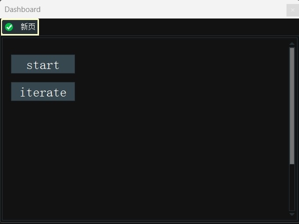
Add 2 input tools—“button” controls to the interaction panel. Double-click to rename them to start and iterate. Middle-click the button and select the corresponding exposure property binding.
Connection node.
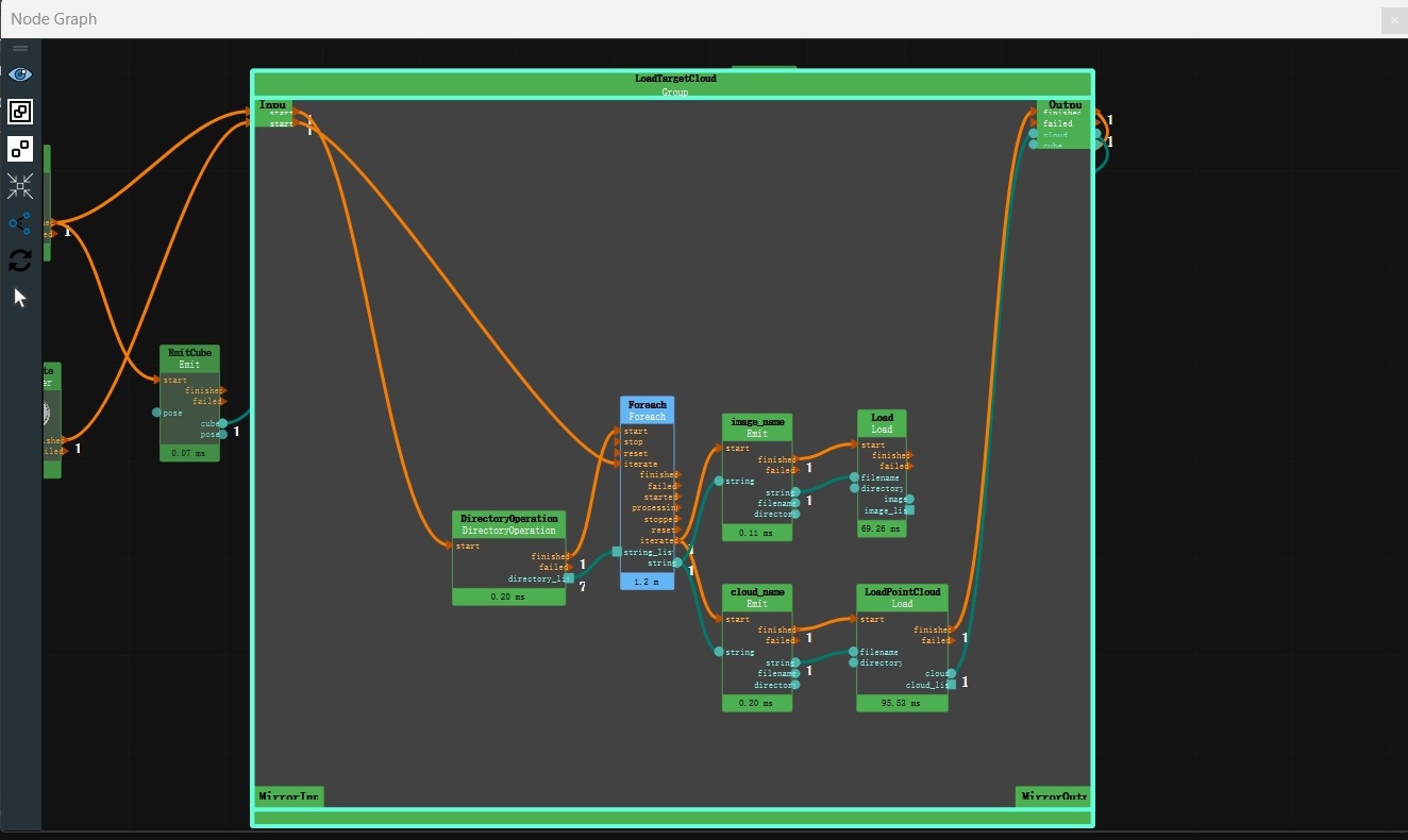
Click the RVS run button. When clicking the
startbutton on the panel, the subsequent operators are triggered. When clicking theiteratebutton on the panel, the offline data in the test_data folder is iterated.
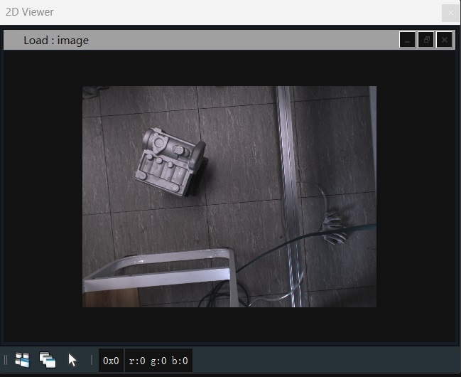
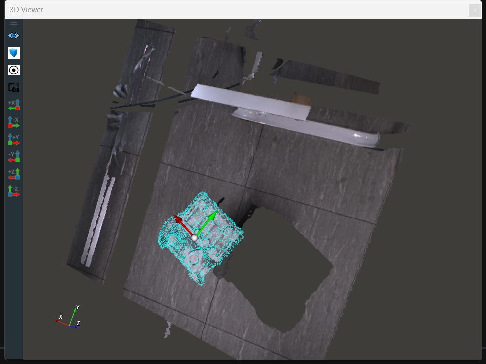
Run Result
As shown below, the currently iterated image is displayed in the 2D view, and the currently iterated point cloud is displayed in the 3D view.
Cropping the Target Point Cloud
After loading the target point cloud data, remove the background point cloud and filter out the working area.
Steps
Add Emit and CloudSegment nodes to the node graph.
Set node parameters.
Set Emit node parameters:
node_name → EmitCube
type → Cube
pose → -1260 -856 621 -180 -178 173
width → 0.5
height → 0.5
depth → 0.2
cube →
Visible
Set CloudSegment node parameters:
type → CropboxSegment
cloud →
Visible → 90
Note
The CloudSegment operator is used to cut out the required point cloud based on the given cube.
Connection node.
Click the RVS run button. Click the
startbutton on the panel.
Run Result
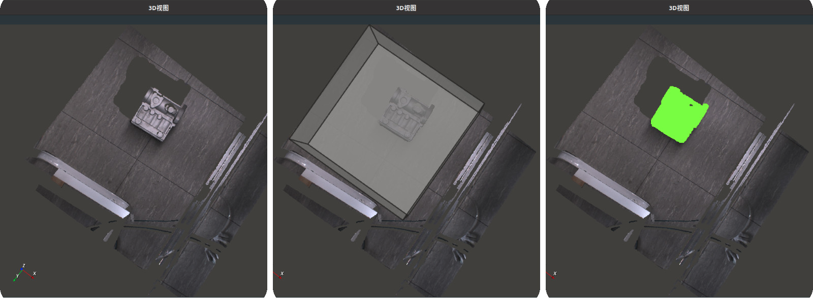
As shown below, the point cloud before and after cropping. The left image shows the point cloud before cutting, the middle image shows the generated cube, and the right image shows the cropped point cloud (green part).
Template Matching
After completing the above steps, the model point cloud and scene point cloud are ready. Next, use the Match3D node to obtain the optimal transformation result coordinates and perform spatial transformation on the template point cloud based on this pose to align it precisely with the target point cloud.
Steps:
Add Match3D and Transform nodes to the node diagram.
Connection node.

Right-click the Match3D node and open the
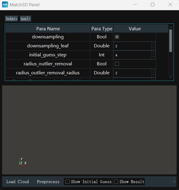
Match 3D Panel:downsampling → Checked
downsampling_leaf → 2
initial_guess_step → 4
Click
Load Point Cloudin theMatch 3D Panelto load the scene point cloud.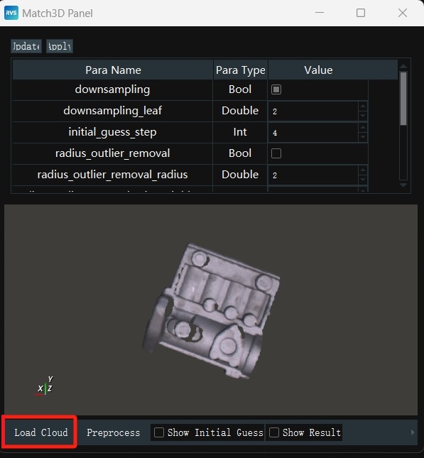
Click
Preprocessingin theMatch 3D Panelto downsample the scene point cloud, improving operator execution efficiency.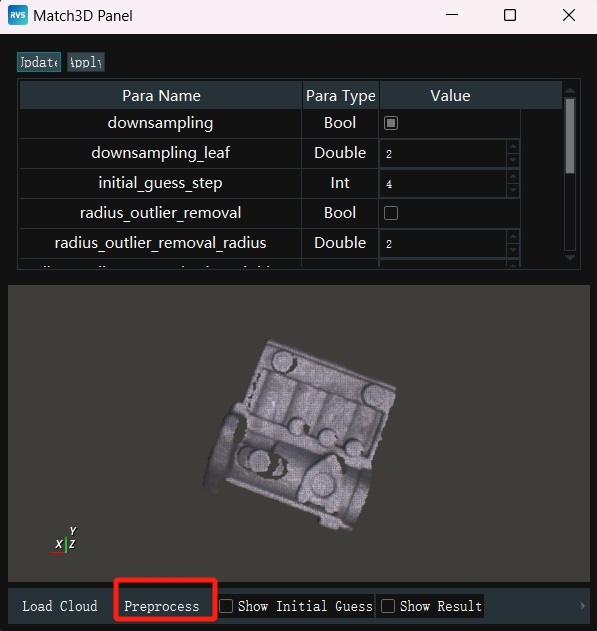
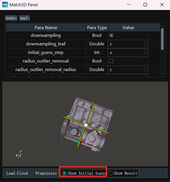
Check
Show Initial Guess Coordinatesin theMatch 3D Panel.Ensure that the Oxy plane of the point cloud model is parallel to the Oxy plane of the scene point cloud. However, there may be coordinate axis conversions, such as the X (Y) axis of the model point cloud being converted to the Y (X) axis of the target point cloud.
To address the above coordinate axis conversion issue, use the center point of the minimal bounding box of the scene point cloud as the reference, rotate it 90° along its Z-axis sequentially, generating 4 different poses (pose). These 4 poses will serve as initial guesses, ensuring that at least one is close to the true value.
Check
Show Resultin theMatch 3D Panelto display the matching result.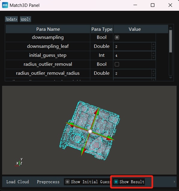
When the matching result meets the requirements, click
√to save the panel parameter settings.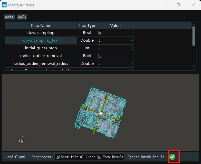
Set Transform node parameters:
type → cloud
cloud →
Visible →180
Click the RVS run button, click the
startbutton on the panel to start matching. When clicking theiteratebutton on the panel, iterate through the target point clouds in the offline data for template matching.
Template Matching Results
As shown below, the following are displayed in the 3D view:
Original color point cloud: Represents the target point cloud, i.e., the point cloud data in the actual scene.
Red point cloud: Represents the position and pose of the template point cloud before matching.
Blue point cloud: Represents the template point cloud after spatial transformation, aligned with the target point cloud.
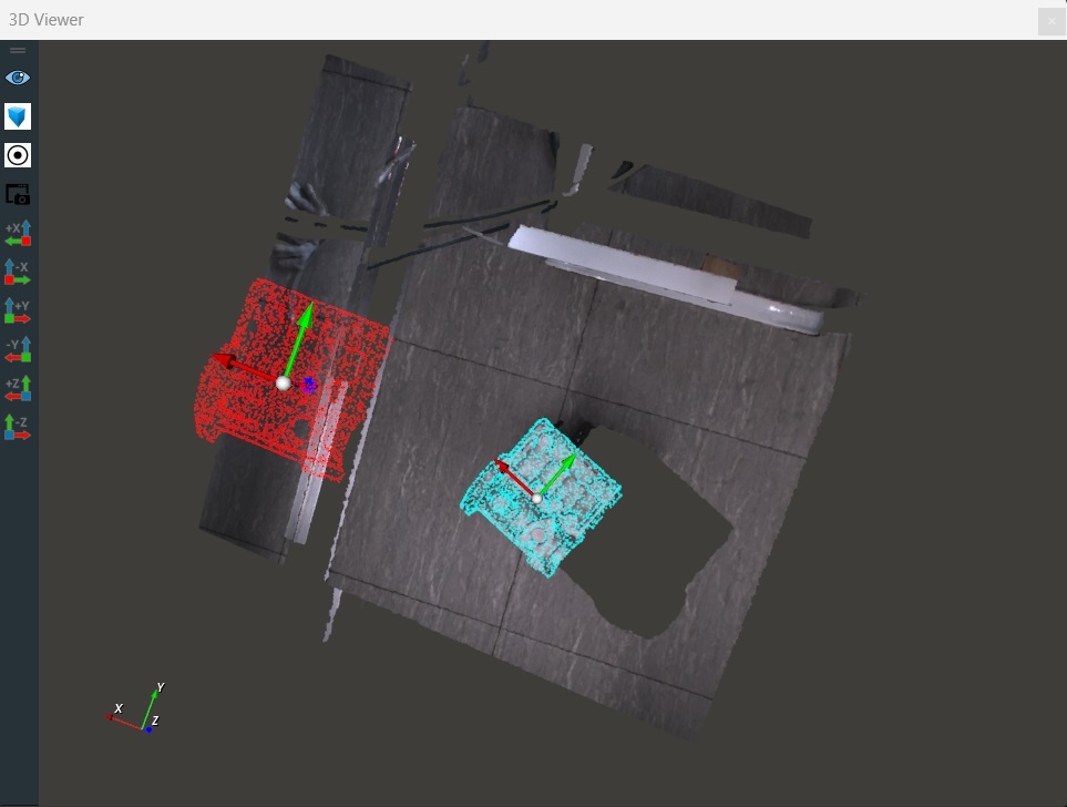
Through the above visualization results, the performance and accuracy of the template matching algorithm can be clearly evaluated.
At this point, you have completed all the content of this document. Thank you for your patience in reviewing it. We believe you now have a good understanding of the RVS software and can independently create your own unique projects. If you encounter any issues during use, please provide feedback promptly by sending an email to rvs-support@percipio.xyz!