ImageCrop
The ImageCrop node is used to crop 2D images.
Cutting Method:
Enter the x1,y1,x2,y2 properties of the image clipping for cutting.
Box select ROI in 2D view for cutting.
Node parameter
x1:The column coordinates of the starting point of the image crop.y1:The row coordinates of the starting point of the image crop.x2:The column coordinates of the ending point of the image crop.y2:The row coordinates of the ending point of the image crop.image:Sets the visual properties of an image in a 2D view. Open image visualization.
 Turn off image visualization.
image_list:Sets the visual properties of the image list in 2D view. The property value description is consistent withimage.
Data signal input and output
Input:
Note:Select one of the data signals to input according to the requirements.
image:Data type:Image
Input content:Image to be cut
image_list:Data type:ImageList
Input content:List of images to be cut
Output:
image:Data type:Image
Output content:After cutting the image
image_list:Data type:ImageList
Output content:After cutting the image list
Functional Demo(Cut using attribute values)
Use the ImageCrop node to cut the banana part of the image to be cut.
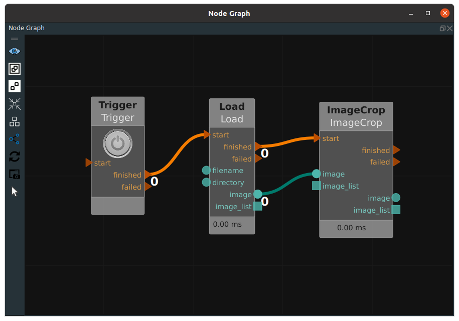
Step 1: node preparation
Add Trigger, Load, ImageCrop nodes to the node graph.
Step 2: Set the node parameters
Set the Load node parameters:
type → Image
filename →
 → Select image file name ( example_data/images/image.png )
image →
Set the ImageCrop node parameters:
x1 → 0
y1 → 0
x2 → 700
y2 → 500
image →
Note:When the mouse stays on the 2D picture, the coordinates of the current pixel can be displayed below the 2D view.
Step 3: Connect node
Step 4: Run
Click the Run button of RVS to Trigger the trigger node.
Running result
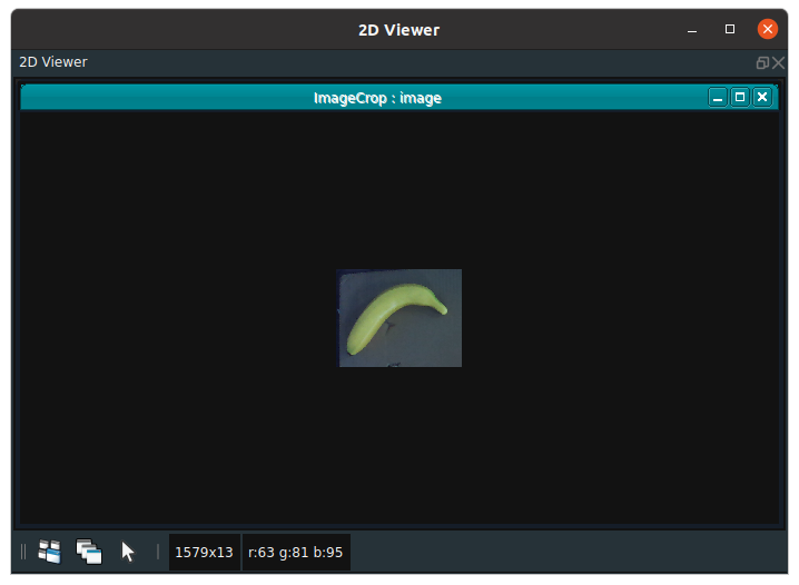
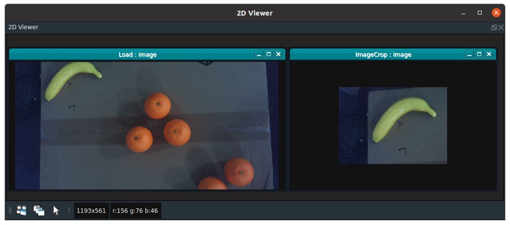
As shown in the following figure, the results of the Load and ImageCrop nodes are displayed in the 2D view. The ImageCrop node intercepts the 700*500 portion of the banana image.
Functional Demo(Select ROI for cutting)
Use the ImageCrop node to cut the banana part of the image to be cut.
Step 1: node preparation
Add Trigger, Load, ImageCrop nodes to the operator graph.
Step 2: Set the node parameters
Set the Load node parameters:
type → Image
filename →
→ Select image file name( example_data/images/image.png )image →
Step 3: Connect node
Step 4: Run
Click the Run button of RVS to Trigger the trigger node.
Locate the visual image of the ImageCrop node in the 2D view and click the
Normal Modebutton in the following image.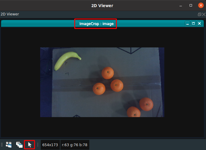
Click the
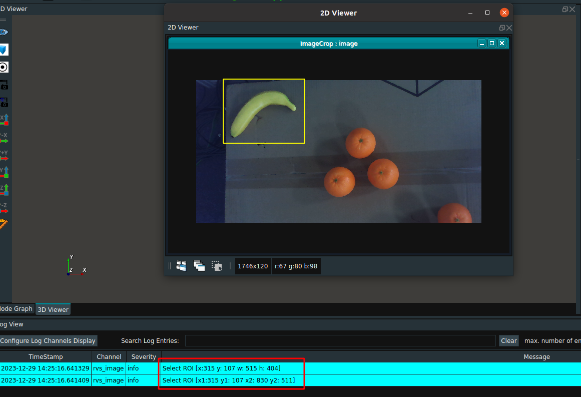
normal modebutton to change tobox selection mode, select the area to be cropped in the image (banana part), the yellow box in the following figure is the part that has been framed. Displays x1,y1,x2,y2 of the selected parts of the box in the log view.Note:To uncheck the box, click the free area of the image loaded by the ImageCrop node.
Trigger the Tigger node again.
Running result
As shown in the following figure, the result of the ImageCrop node is displayed in the 2D view. Capture the banana portion of the image.