When you get this document to RVS developer community to download binpick_runtime.zip deep box grab tutorial supporting data. After decompression, its contents should include:
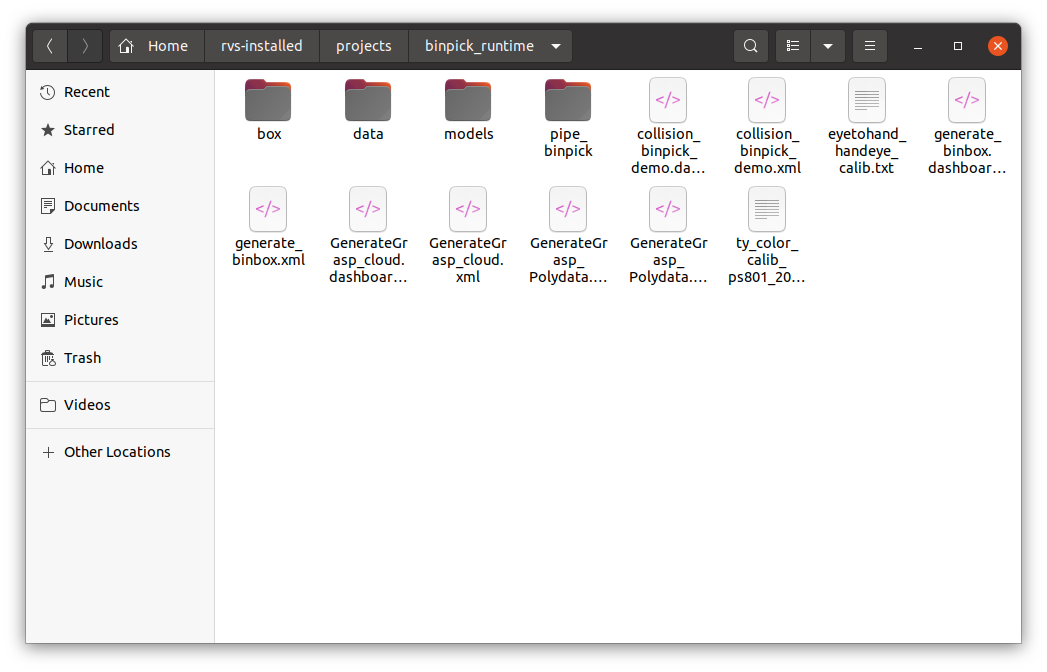
box contains the box point cloud used in the demonstration in this case.
data contains the robot model and the tool model used in this case. If you need other models, please download them from the RVS Software distribution model website.
Note:If there is no robot model, please contact the Tuyak RVS developer to add it.
models contain the corresponding grasping strategies of the obstacle model used in this case and the target object model.
pipe_binpick contains the offline data used in this case, as well as the weights and configuration files for AI training.
collision_binpick_demo.xml is used for deep box capture demonstration, and contains AI identification, template matching, and robot collision avoidance modules.
Note:collision_binpick_demo.dashboard.xml is the corresponding dashboard.
generate_binbox.xml is used to generate a standard Binbox model, which is suitable for the creation of a regular cube shape Binbox.
Note:generate_binbox.dashboard.xml is the corresponding dashboard.
GenerateGrasp_cloud.xml is used to generate a fetching strategy from a surface cloud on a target object. At this point, tcp should use robotic tool end points.
Note:GenerateGrasp_cloud.dashboard.xml is the corresponding dashboard.
GenerateGrasp_Polydata.xml is used to generate a fetching strategy from the polydata model and tool model of the target object. At this time, the tcp should use the robot flange center point.
Note:GenerateGrasp_Polydata.dashboard.xml is the corresponding dashboard.
eyetohand_handeye_calib.txt is the result of hand-eye calibration in this case.
ty_color_calib_ps801_207000129939.txt is the parameter file of the camera.
All files used by the case are saved in binpick_runtime
Note:If you do not want to adjust the file path in XML. You can rename binpick_runtime to runtime.
Note:The version of RVS software used in this document is 1.5.559. If there is any problem or version incompatibility in use, please contact us at rvs-support@percipio.xyz!
Motion planning function introduction
RVS adds a motion planning function module for deep box grabbing and other application scenarios.In addition, the collision avoidance (optional) function is embedded in the module to ensure that the robot can complete the extraction of the object without collision. The whole module contains 6 special nodes,they are MotionplanningResource node,ObjectSceneOperator node,CreateBinBox node,PlanGrasp node,GenerateGrasp node,GraspDebug node.
Basic definition introduction
Grasp
The robot grabs or absorbs the detection target (or other ways), which is uniformly represented by grabbing.
Note:The following description of the motion planning function module takes the deep box grabbing application scenario as an example, and the collision avoidance function is used by default.
Binbox and standard binbox
The Binbox is the container that holds the detection target.For the simple fluted form of the box, the shape is a cube shape, the concave part is also a cube shape, RVS defines it as a standard box, and provides it with a standard model creation method and positioning method.
Create Binbox process see Generate_binbox.
Grasp target
Objects grabbed by the robot end tool. Each grasping target has its own physical model and body coordinate system. In the deep box grasping application of RVS, the default place surface of the target in the Binbox is the Oxy plane of its body coordinate system. The length, width and thickness of the target mentioned below are also the length of x axis, y axis and z axis under the target body coordinate system by default.
Grab target model file
That is, the 3D file that captures the target physical model needs to be converted into polydata data format for RVS to useThe target model file used by RVS can be either the full model file of the target or the upper surface model file of the target.When the thickness of the target is relatively thick, if only the upper surface model of the target is involved in the collision avoidance calculation, the robot may hit the side of the target or penetrate through the model during the actual grasp. In this case, the customer must provide the complete digital model file of the target for RVS to perform collision avoidance calculation.When the thickness of the target is thin, RVS only needs to involve the upper surface model of the target in collision avoidance calculation. In this case, the customer does not need to provide a complete model file. RVS can directly shoot the upper surface point cloud based on the target object, and then use the point cloud processing as the upper surface model of the target.
Note:In cases where only the upper surface model of the target is needed, the customer can also provide the raw digital model, which is more accurate than the model created by the point cloud.
RVS can also generate a complete digital analog file by shooting the point cloud, but the accuracy is low and the steps are cumbersome, if necessary, you can contact the Tuyang RVS developer.
Coordinate system
The coordinate system involved in the application of RVS motion planning includes the robot coordinate system, the camera coordinate system, the body coordinate system of the grasping target, the body coordinate system of the Binbox, the body coordinate system of the other obstacles, and so on. In the motion planning operation, we need to uniformly convert to the robot coordinate system, so we will mention hand-eye calibration, Binbox positioning and other operations in the following operation process, the purpose is to convert the coordinate system.
Note:Under the robot coordinate system, the attitude representation of the robot itself includes the flange coordinate system, the end tool coordinate system and so on.
In addition, when the surface point cloud model or the complete point cloud model is used in the volume coordinate system of the captured target, the center of the model is offset in the direction of the z axis.
Grasp position
Based on the volume coordinate system of the grasping target, multiple groups of grasping points can be defined, and each grasping point can define multiple groups of grasping angles. A grasp point and a grasp Angle, that is, a grasp position, is represented by a Pose in RVS. RVS provides a method for visually creating grab poses based on the target model.
Grasp strategy
A grasping strategy corresponds to a set of grasping pose modes based on the coordinate of the target model, including pre-grasping pose, grasping pose and lifting pose. As shown in the following picture.
Create a fetching strategy process see generate grasp.

When a grasp pose is determined using RVS, the pre-grasp pose and the lift pose can be obtained by inputting the pre-grasp offset parameters and the lift offset parameters, respectively.Among them, the pre-grasp pose is shifted upward along the z-axis of the actual detected target. The lifting attitude is offset along the Z-axis of the robot coordinate system.In actual operation, the robot flange (or tool end) first moves to the pre-grasp position, and then moves to the grasp position along the Z-axis direction of the target, and then performs operations such as inhalation or claw clamping, and then moves vertically up with the grasp to the lifting position, and then carries out subsequent custom operations. As shown in the following picture.

Detection target list
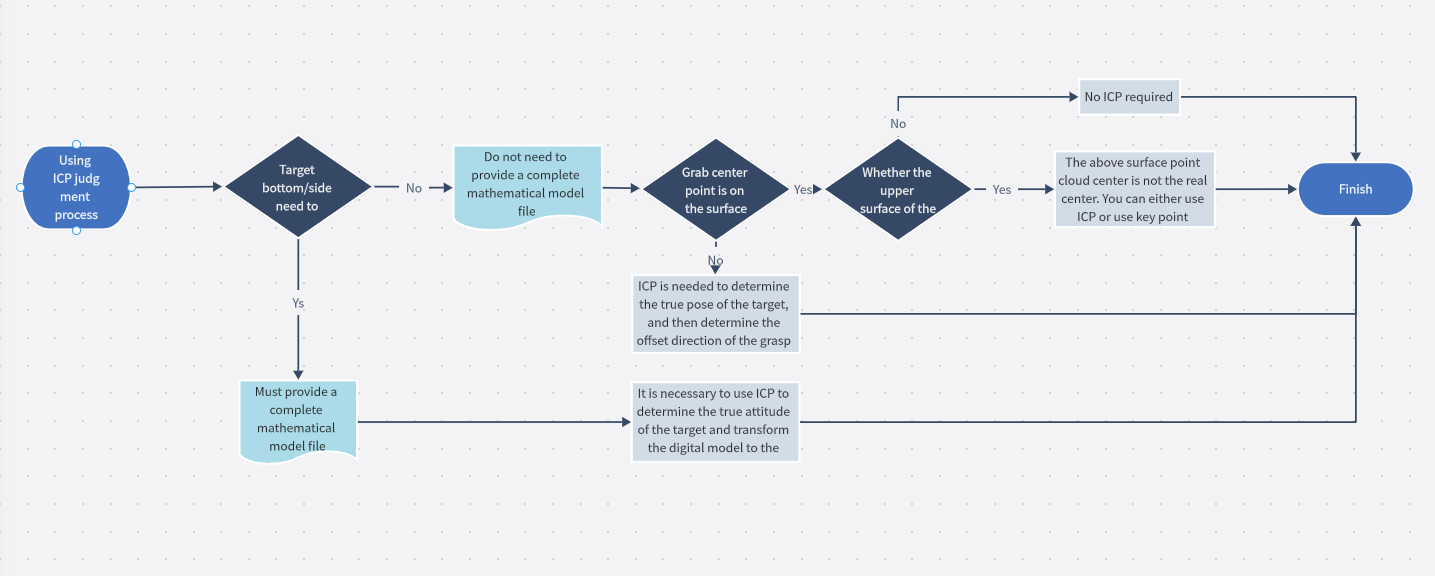
The actual point cloud in the Binbox is processed by coordinate transformation, from the depth camera coordinate system to the robot coordinate system, and then point cloud processing, and finally the PoseList of all the targets detected is the detection target list. In the detection operation of RVS, the central pose of the surface point cloud on the target is obtained first. If it needs to be converted into the central pose of the complete model, it needs to be shifted along its Z axis by an appropriate length. The x/y axis direction definition of the central pose of the upper surface obtained by RVS detection operation is random, and when the point cloud of the upper surface is partially blocked, the central point positioning of the pose will also be inaccurate. In order to obtain higher positioning accuracy, it is recommended to carry out template matching processing on the central pose.
For more specific instructions on whether to use template matching, see the following flowchart.
Motion planning scene
The virtual space in which RVS performs motion planning operations uses a robot coordinate system for its internal motion planning operations (including collision avoidance operations). In RVS, a motion planning scenario corresponds to a MotionPlanningResource (motion planning resource) node. When creating a motion planning resource, it is necessary to bind a grasping target and provide the model file and grasping strategy file of the grasping target.
Binpick process
Robot modeling
When the desired robot is not available in the RVS robot module library, please provide the robot module file and contact the Tuyang developer to model the robot. For loading tools, such as suction nozzle, suction cup, clamp claw, etc., the customer needs to provide the corresponding 3D model. If the camera needs to be mounted on the end of the robot, the customer needs to design the camera mount and provide a model of the mount. We will provide you with the digital and analog files of Tuyang cameras, and provide technical support and solutions.
Hand-eye calibration
Hand-eye calibration is performed based on how the camera is mounted, see the auto-palletizing Hand-eye Calibration Introduction documentation for details.
This case uses eyetohand mode and the calibration results have been saved to eyetohand_handeye_calib.txt.
Binpick main process
This chapter will introduce the operation flow of binpick and the main modules of building XML process in detail.
Operation process
Load collision_binpick_d.xml 。
The Dashboard is shown below:
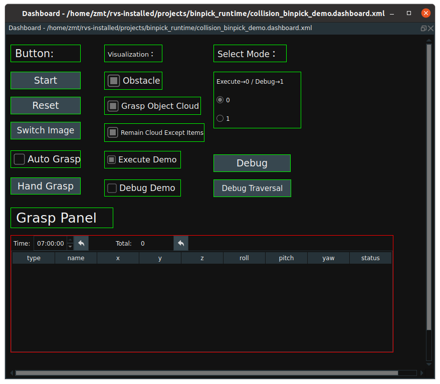
Start:Once clicked, start traversing the offline data in the pipe_binpick/data folder.Reset:Re-run the case presentation. ClickResetand then clickStartto restart the presentation from the first image.Switch Image:Once clicked, walk through the next image.Auto Grasp:When checked, all grabable objects are automatically captured in a single image.Hand Grasp:IfAuto Graspis not checked, then manually click this button, you can grab items one by one in a single image in order. Default:Hand Grasp.Grasp Panel:The grab panel displays the grabable item pose.Obstacle:Check it to display all obstacles in 3D view.Grasp Object Cloud:Check it to display all grabable point clouds in 3D view.Remain Cloud Except Items:Check it to display the remaining point cloud in 3D view except for the item.Select Mode:Grasping strategy calculation model. Select the corresponding grasping strategy calculation mode in the dashboard.0:Excecute mode。
1:Debug mode。
Execute Demo:After checked, the pre-grab position, grab position and uplift position of the robot moving to grab the item in execute mode will be displayed in 3D view.Debug Demo:After checking, when the robot collides, the collision details of the robot model under each strategy are displayed in the 3D view.Debug:When mode 1 (debug) is selected, click this button to enter debug mode.Debug Traversal:Traverse all policies generated by the PlanGrasp node.
Set the Settings in the Dashboard to:
0: Execute mode. Check theExecute Democheck box and the dashboard is shown below.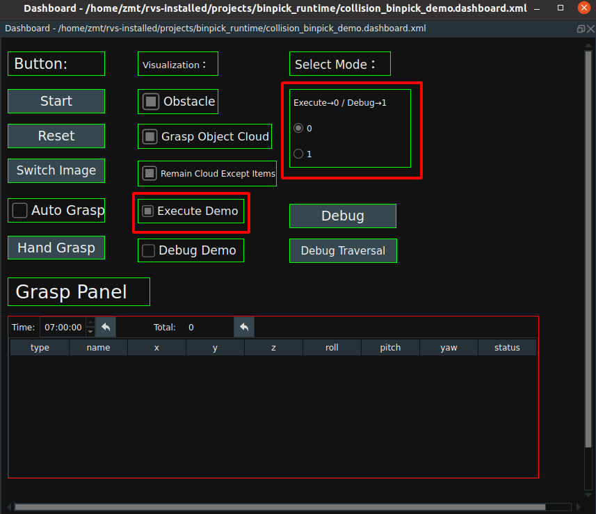
Click the RVS Run button, and the resource node and part of the node are initialized. As shown in the picture below:
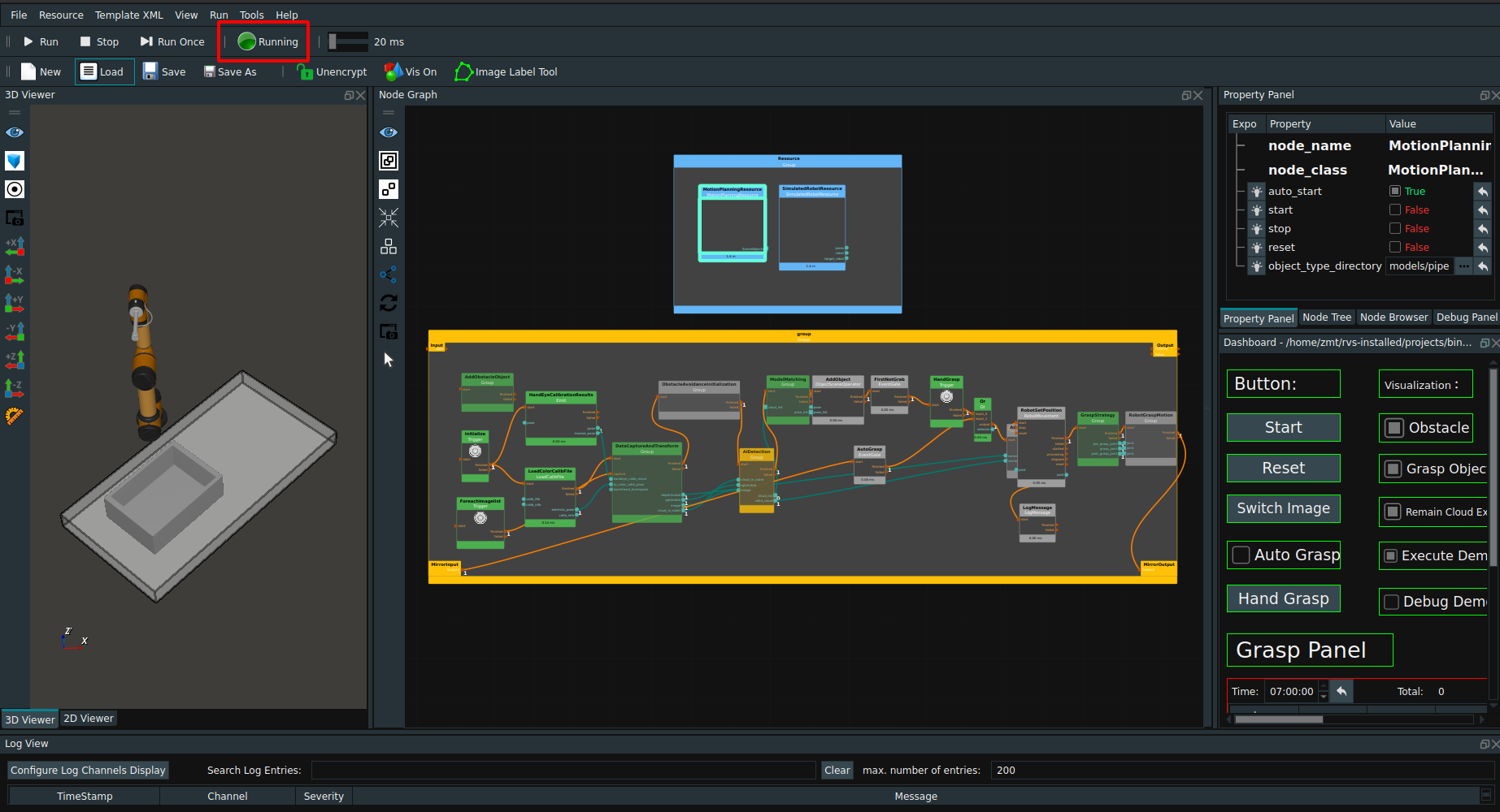
Click the
Startbutton in the dashboard. When triggered, the grabable item pose in the first picture is displayed in the grasp panel, and the grab status is “X”.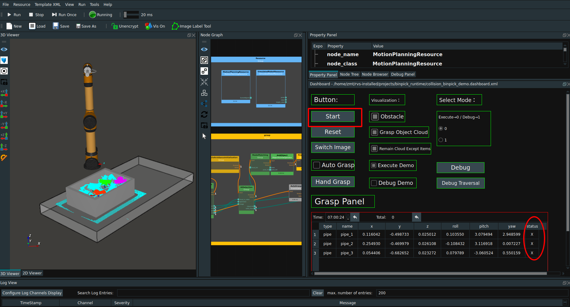
Default manual grab mode. At this time, click
Hand Graspto grasp the first target object with the optimal grasp strategy, and RVS will automatically guide the robot to perform the grasp action and display it in the 3D view. At the same time, theGrasp Paneldisplays the grab status in real time. After the fetching is complete, the status is displayed as “O”.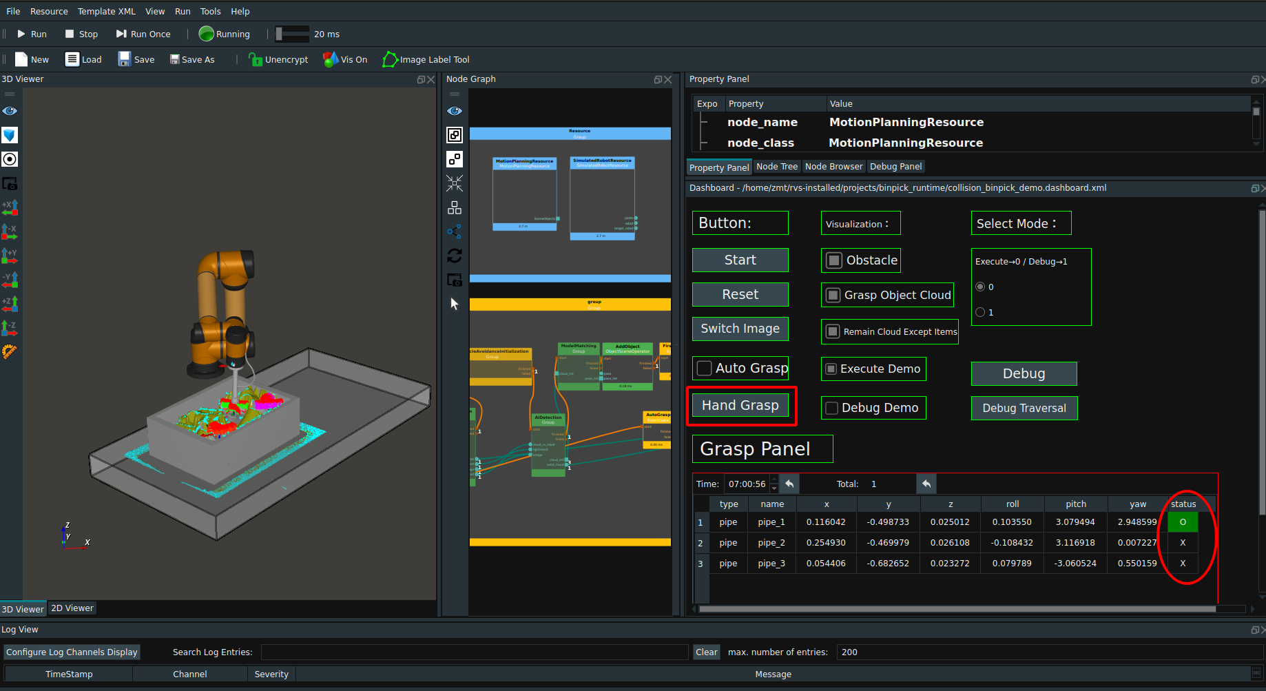
If
Auto Graspis checked, all grabable items are automatically grabbed.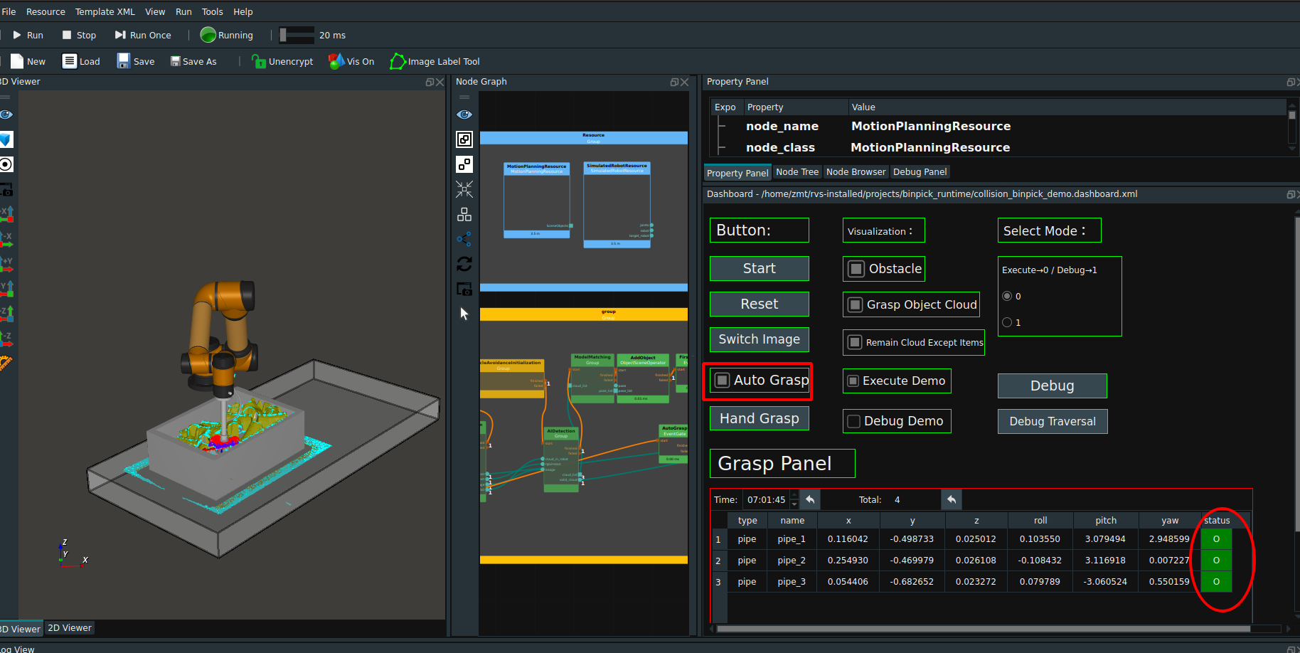
When the log prompts “this picture has no capture target, please switch to the next one”, click the
Switch Imagebutton in the dashboard. The next set of offline data will be switched for grabbing, and this operation will be repeated.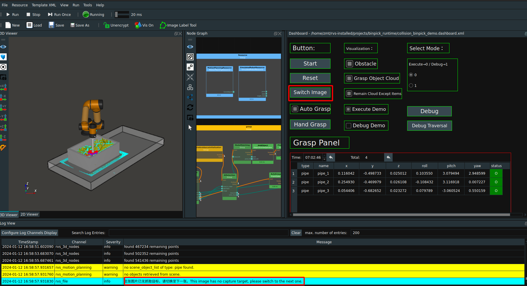
If you want to start over during execution click the
Resetbutton and clickStartagain to start over from the first image in the pipe_binpick/data folder.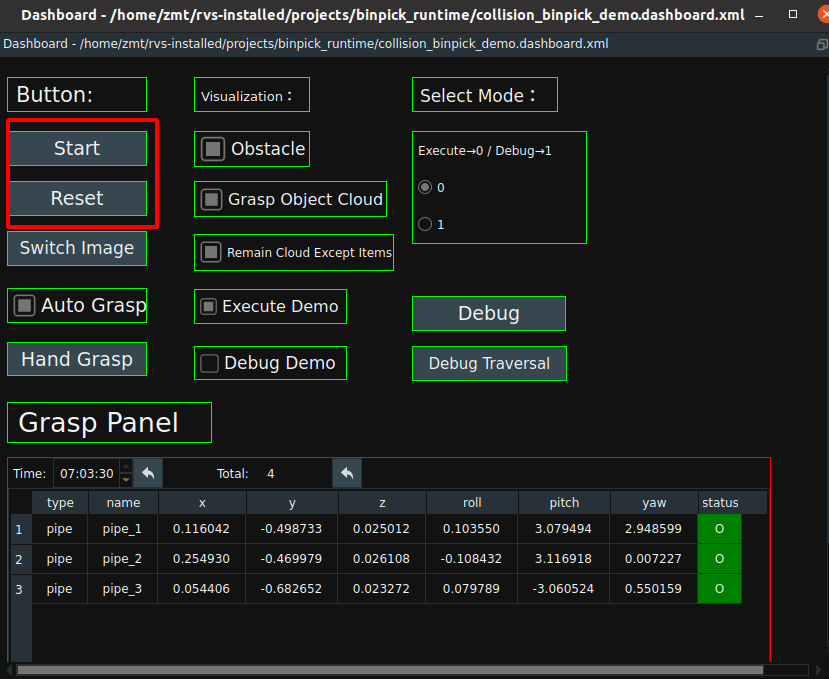
When a warning message (red rectangle box in the following figure) appears in the log and the robot stops grabbing, it indicates that the robot has no grabbing strategy.
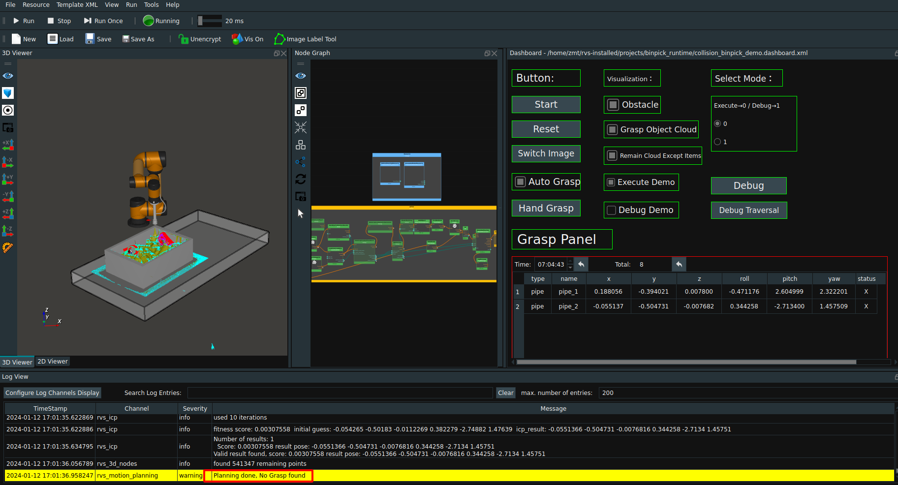
At this time, the calculation strategy mode is set to 1 in the dashboard.That is, in debug mode,Turn off the
Execute Democheckbox,Check theDebug Democheck box,Click theDebugbutton,Click theDebug Traversalbutton a few more times,Robot collision details are traversed in turn and displayed in 3D view, while specific information about the collision details of the current grasping strategy is displayed in the log.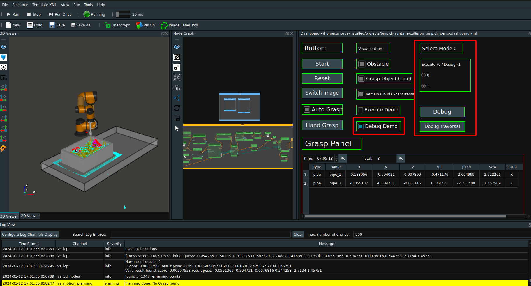
The above is the operation process of this case. When the offline data file traversal is complete, you can click the
Startbutton in the dashboard to re-present the case.
Process introduction
collision_binpick_demo.xml ,That is, the main process engineering file, as shown below.
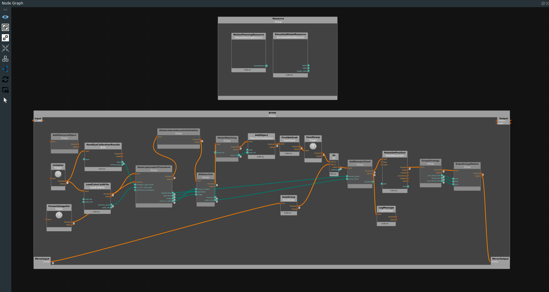
Resource class Node Management
MotionPlanningResource.Object type file loading directory, the folder needs to contain the object model file, as well as the target object grasping strategy.
SimulatedRobotResource.Select the corresponding robot model and tool model and check enable collision avoidance.Note:If RVS is required to actively control the robot, it can be replaced with the corresponding robot control resources.
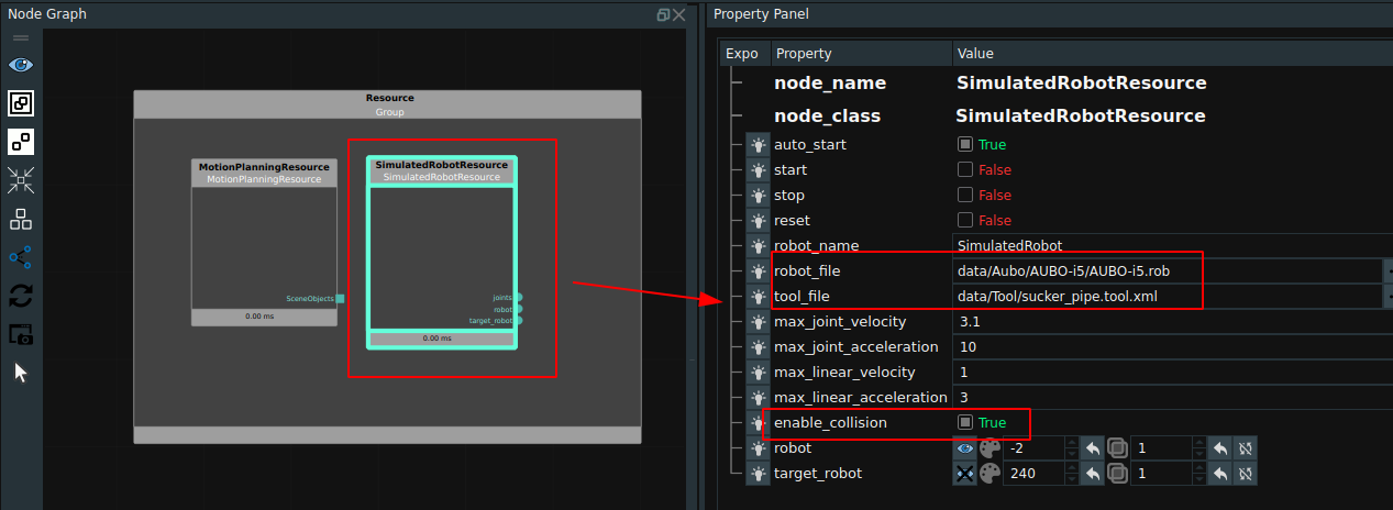
Add collision avoidance
In the
AddObstacleObjectGroup, the corresponding scenes and obstacles can be loaded and created.In this case, a cube was created to represent the desktop model and added to the scene as an obstacle, while the Binbox model file was loaded to add to the scene as an obstacle. In the actual project, you can add the required obstacle model according to the need.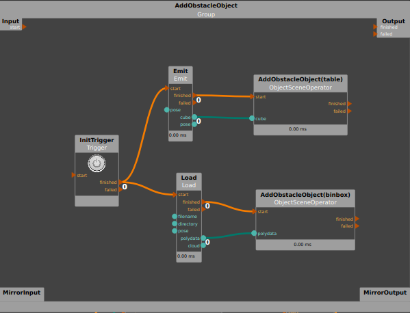
Set hand-eye calibration conversion parameters
Paste the hand-eye calibration result in the node
HandEyeCalibrationResults.Load the rgb lens parameter file of the Tuyang camera in the
LoadColorCalibFilenode.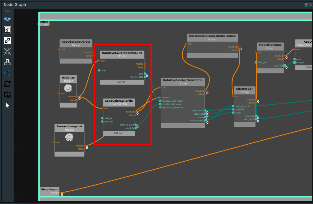
Data acquisition and conversion
The
DataCaptureAndTransferGroup can be added directly in theGroup XMLnode library of the Node Browser.The Group supports data acquisition in different modes, and converts the acquired data directly to the robot coordinate system using hand-eye calibration results.
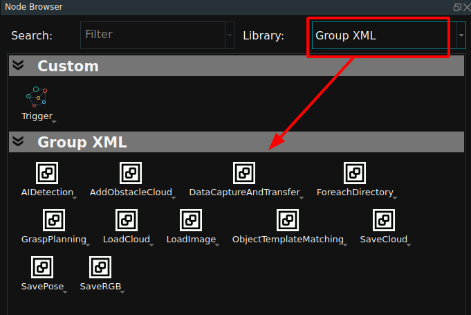
This case uses the eye to hand mode conversion,Set the offline data folder in the
DataCaptureAndTransferGroup →offline or onlineGroup →offlineGroup →ReadDirectoryNamesnode.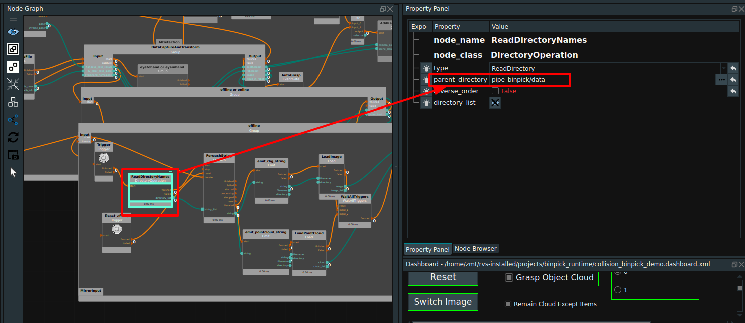
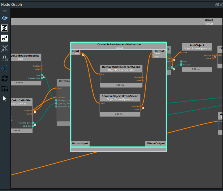
Obstacle avoidance initialization
Used to clear the last participating obstacle avoidance point cloud (obstacle) with the target object. This case clears the last obstacle avoiding point cloud (obstacle) and the target object pipe. As shown in the following picture.
Note:It is normal for the RemoveObstacleFromScene node to warn during the first run because there is no obstacle from the previous run.
AI Detection
Note:According to whether the targets are stacked and adhered to, determine whether AI recognition is needed, and if so, data collection, labeling, and training are also required. Please refer to the case of automatic unpalletizing.
AIDetectionGroup can be added directly in the Node Browser’sGroup XML. The Group is used to sort the point cloud after AI inference and intercept the point cloud list output.
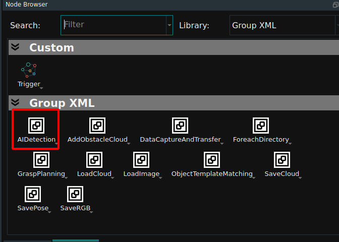
The Group places point cloud cutting, AI reasoning, mapping image Mask, point cloud sorting and other nodes, which can be set according to the actual project. Refer to automatically open buttress case AIDetect. This case is set up in the XML.
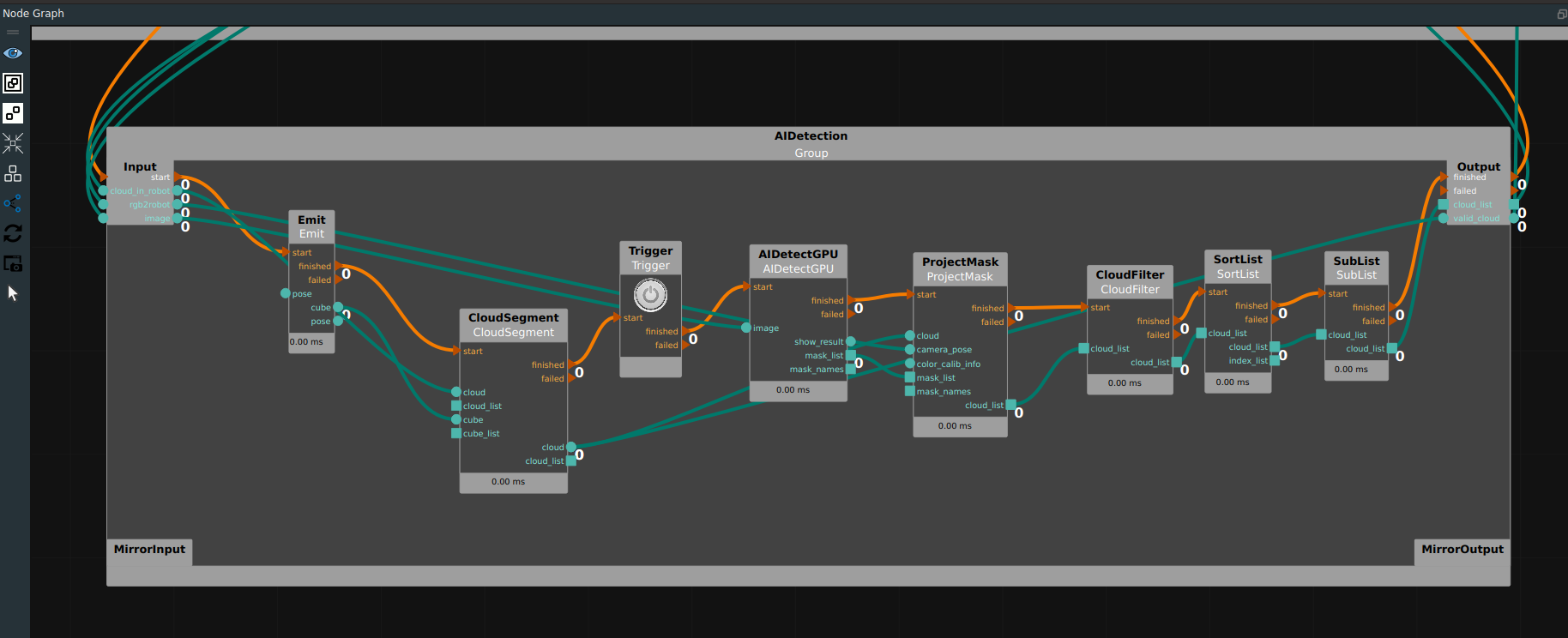
Target model matching
The
ObjecTemplateMatchingGroup can be added directly to theGroup XMLnode library in the Node Browser. The Group is used to process the list of point clouds identified by AI successively and perform model matching.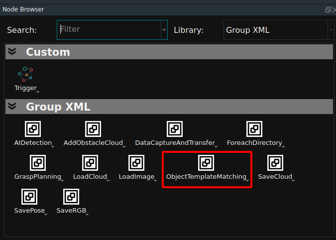
The Group iterates the list of point clouds, then performs model matching and collects the results to generate a list of detection targets. Group is shown in the following figure.
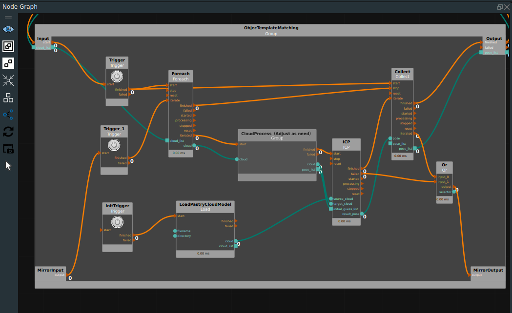
The three input ports of the
ICPnode are the model point cloud, the real surface point cloud, and the real pose estimate.It is shown in the red rectangle box in the following figure.The model point cloud can be mapped to the upper half of the target model using the polygon rendering point cloud node.In order to improve the operation efficiency ofICPnode,In order to improve the operation efficiency ofICPnode, the actual surface point cloud uses the original point cloud after downsampling, and the number of point clouds after downsampling should be balanced with the number of model point clouds. The actual pose estimation is generated byCloudProcess (Adjust ad need)Group.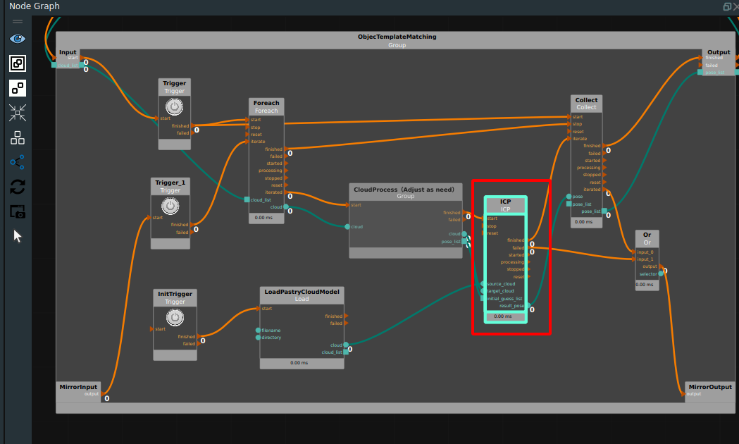
In the
CloudProcess (Adjust ad need)Group, firstly, the original point cloud of the target is preprocessed by plane segmentation, because the original point cloud of the target in this case has a lot of side and bottom information, while the model point cloud only has the upper surface information. The extraction of the upper surface information by plane segmentation can improve the accuracy of ICP model matching. Then, theMiniMumBoundingBoxnode is used to process the surface point cloud on the target to obtain its central presumed pose, and then the inferred pose of the model center is obtained by migrating along the Z-axis. Finally, the inferred pose list is generated.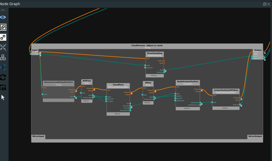
Add items
The
AddObjectnode adds the list of detection target poses obtained from model matching to theMotionPlanningResource. As shown in the following picture.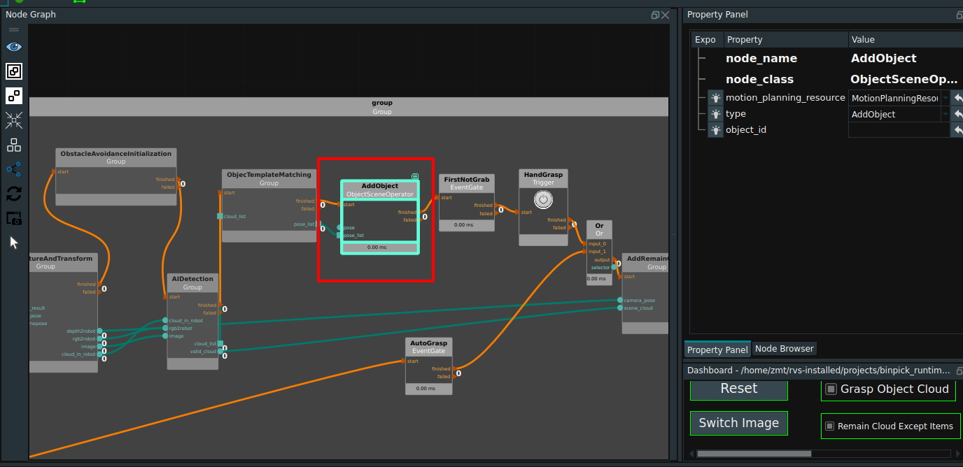
AddObstaclecloud
Add
AddObstaclecloudGroup directly in theGroup XMLnode library of the node Browser.The Group is used to remove all detection target point clouds from the original point cloud, and then add the obtained remaining point clouds to the motion planning scene as collision avoiders.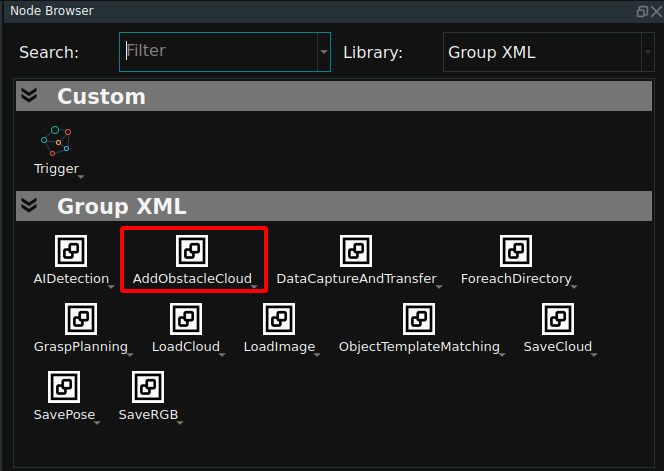
In the
AddObstaclecloudGroup, firstly, the model of the detection target is obtained from the scene, and then according to the Tuyang camera installation pose under the robot coordinate system, the virtual camera is used to render the point cloud of all the target models at the same pose, and the rendered point cloud obtained can be used as the detection target point cloud. Finally, the real point cloud is subtracted from these rendering point clouds, and the remaining part of the real point cloud is defined as remaining point clouds. Finally, these remaining point clouds are added to the scene as collision avoidance objects after converting the data format.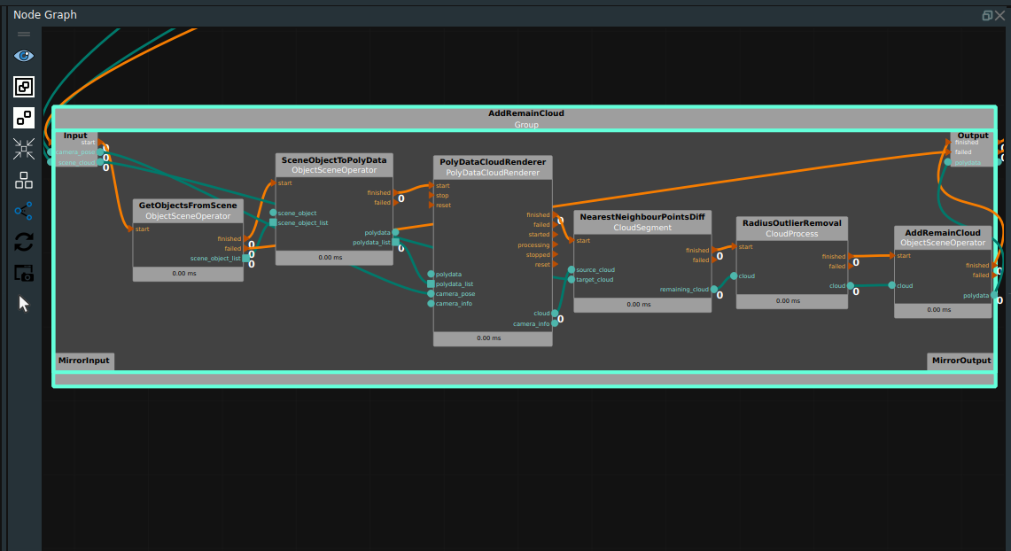
Robot set position
The node is used to set the joint value of the robot at the waiting position before each grasp.
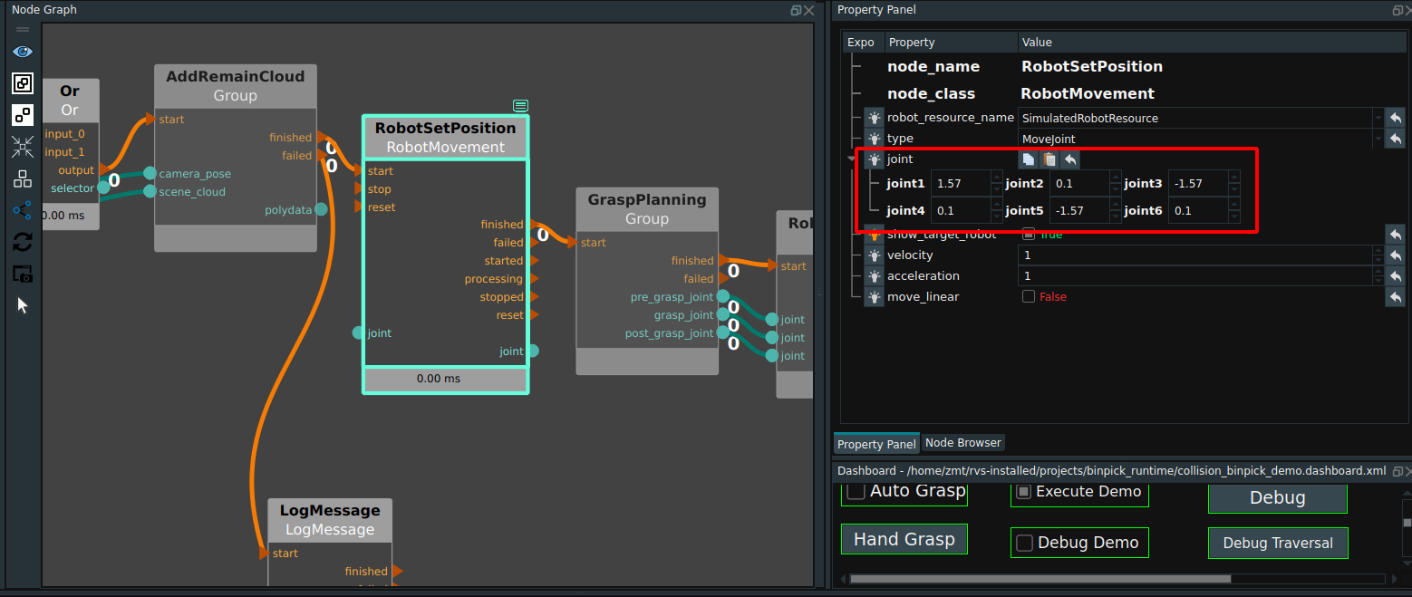
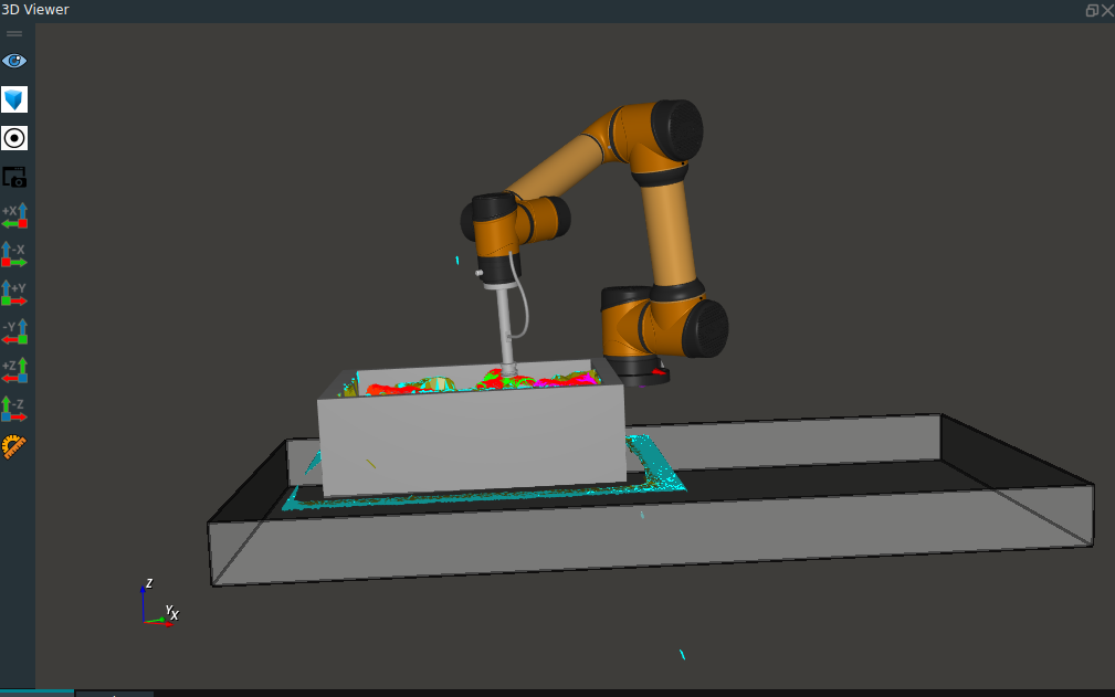
In this case, the location is shown below.
Grab strategy
The
GraspPlanningGroup can be added directly to theGroup XMLnode library in the Node Browser.The Group is used to calculate the grasping strategy. In release mode, the best grasping strategy after collision avoidance will be directly given.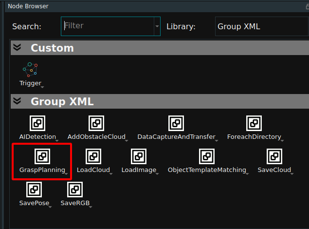
The
GraspPlanningGroup is divided into release mode and debug mode.When the mode selected in the dashboard is
0: execute, when the robot does not collide, the grasping strategy will output a set of joint values of pre-grasping position, grasping position and lifting position to guide the robot to grasp motion; When a robot collides, a warning will occur for the planning grasp strategy, the execution of the PlanGrasp node fails, and the failed port is triggered, as shown in the following figure. In actual projects, the failed port can trigger operations such as box vibration.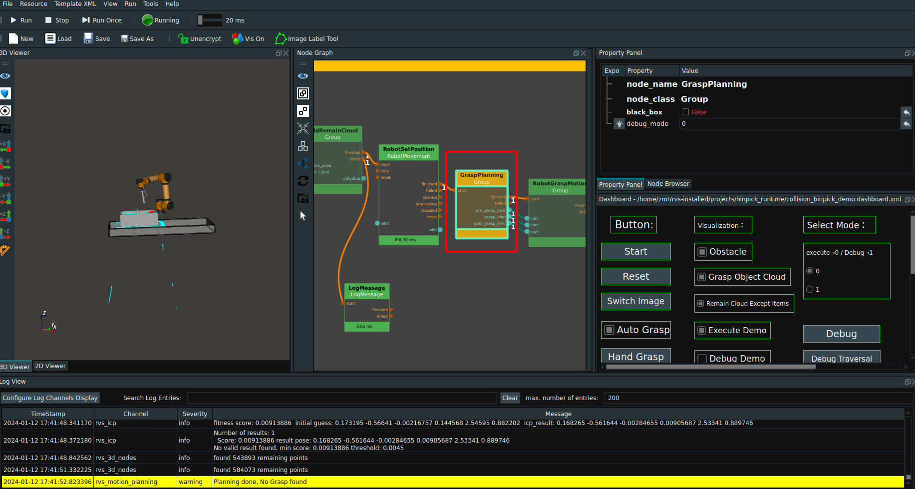
When the mode is selected as
1: Debugin the dashboard, when the robot collides, check the visual property ofDebug Demo, click theDebugbutton to start debugging, click theDebug Traversalbutton to traverse all strategies generated by thePlanGraspnode, and display the collision details of the robot model under each strategy.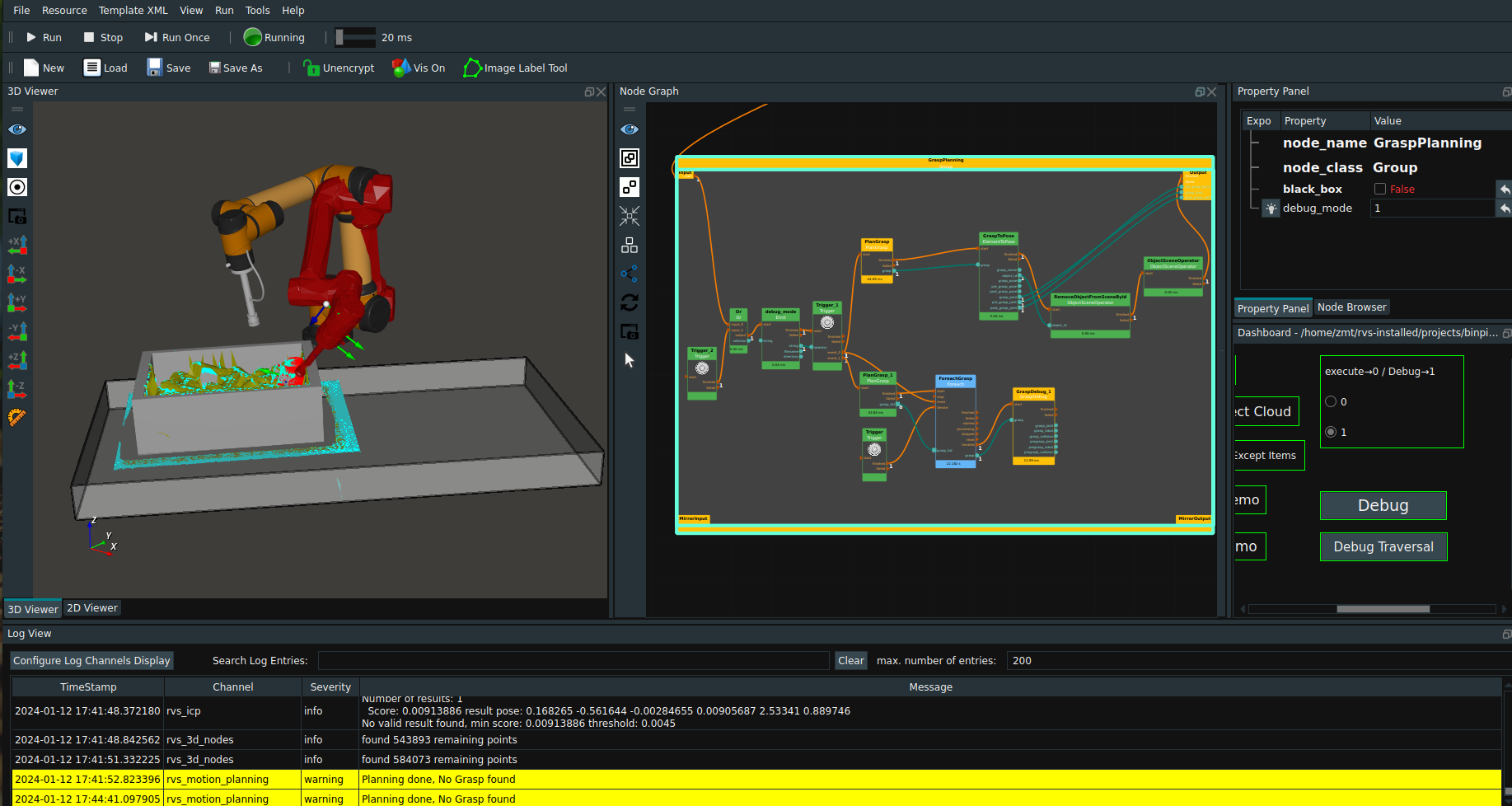
Robot grasping motion
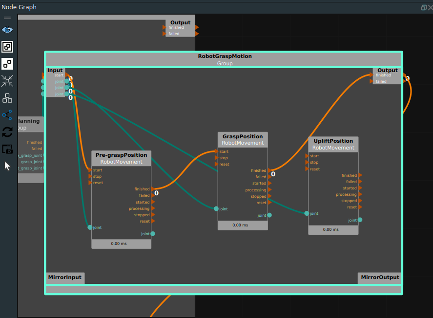
The Group will guide the robot movement through the
MoveJointmode in theRobotMovementnode according to the joint values of pre-grasp position, grab position and Uplift position output by the above strategy. As shown in the following picture.Note:In order to reflect the grasp position, the lifting joint value is not connected, and can be connected if necessary.
Generate Binbox
Standard feed box model creation
Load generate_binbox.xml as shown in the following figure.
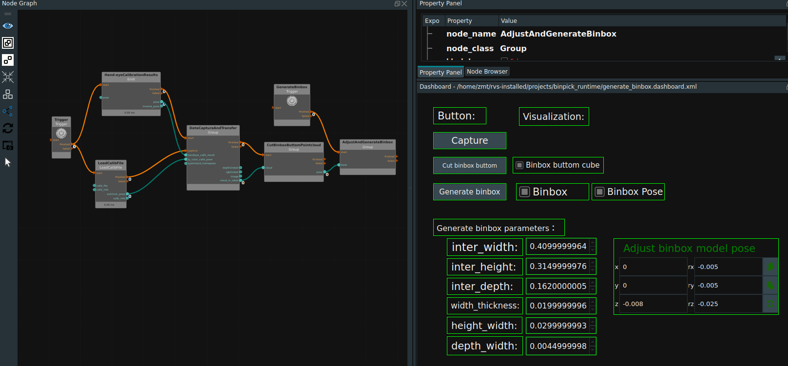
Parameter Settings. This case uses the eyetohand mode.
Paste the hand-eye calibration result in the node
Hand-eyeCalibrationResult.Load Tuyang camera rgb lens parameter file in
LoadCalibFilenode.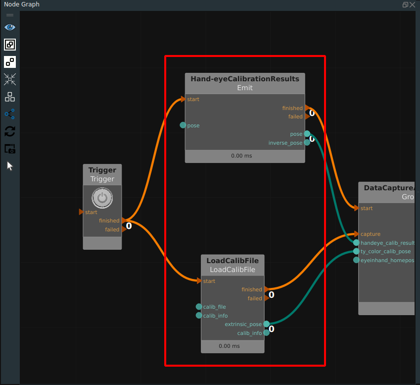
Click the RVS Run button.
Gets the cloud at the bottom of the deep box.
Click the
Capturebutton in the dashboard, and the deep box point cloud will be displayed in the 3D view.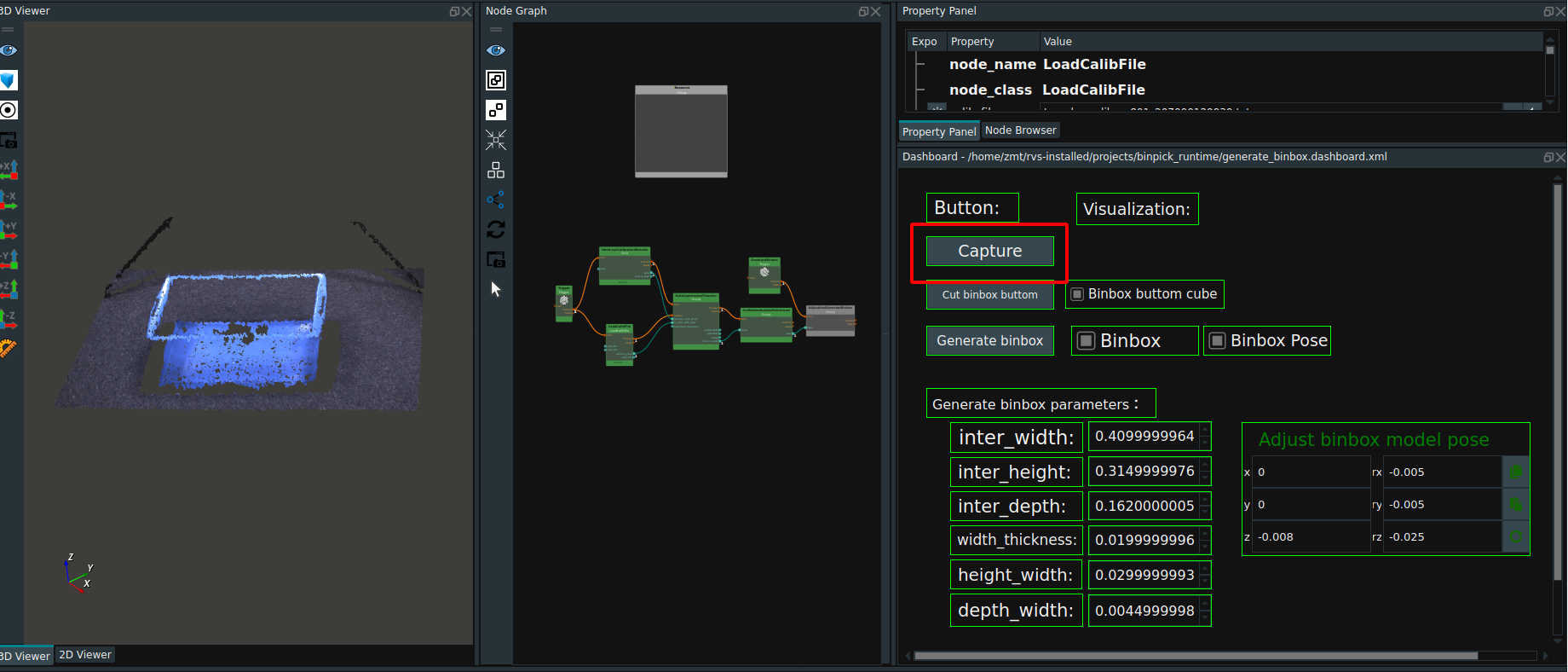
Click the
Cut binbox buttombutton in the dashboardAdjust the size and position of the cube at the bottom of the desired cut deep box.The
Binbox buttom cubecheck box sets the visualization of the cube.Double click cube in 3D view and check theMove Posein the pop-upcube panelto set the size and pose of cube.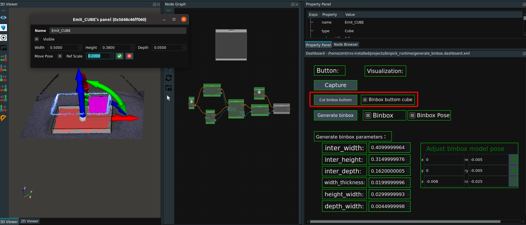
Create a deep box.
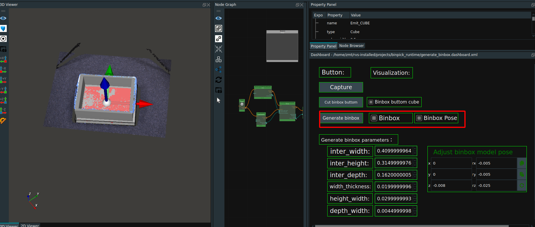
Set the parameters of the deep box in the dashboard (red rectangle box below), Please refer to documentation CreateBinBox.
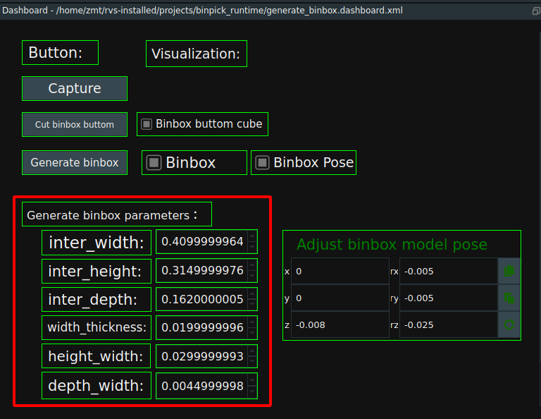
Click the
Generate Binboxbutton in the dashboard. Check theBinbox,Binbox Posecheck box, the 3D view will display the deep box and deep box pose.
Adjust deep box model pose.Observe the overlap degree between the deep box and the point cloud, and adjust the position through the
Adjust binbox model posecontrol in the dashboard. After the parameter setting is completed, click theGenerate binboxbutton in the dashboard again until the position of the deep box and the point cloud have high overlap degree.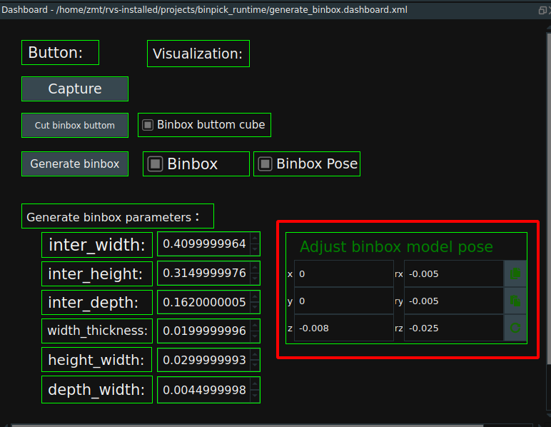
Save the deep box.
In the
AdjustAndGenerateBinboxin theGenerate binboxnode can set the creation of deep box to save the location and name. Click theGenerate binboxbutton in the dashboard to save the binbox file.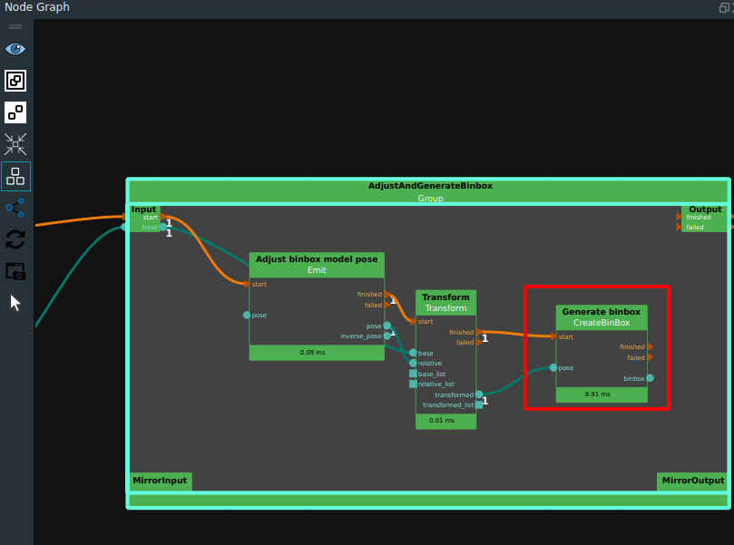
Note:The name of the deep box saved in this case is testbinbox.obj, while the name of the deep box used in later case projects is binbox .obj. Because this case is for teaching use, to avoid learners in the process of use due to improper operation and subsequent project problems.
Non-standard feed box model creation
For non-standard boxs, the customer needs to provide a box model file. After the Binbox is placed and fixed in the work scene, the robot panel is controlled according to its actual position to move the robot to several corners of the Binbox, directly estimate the pose of the Binbox in the robot coordinate system, and then move the pose of the model to this position in RVS, and then the point cloud can be photographed for comparison and fine adjustment. In addition, for non-standard Binboxs, when the Binbox structure is relatively simple, it can also be modeled by creating multiple cubes.
Generate grasp
Creating a grasping strategy is divided into two categories:
The first type is that the customer’s robot uses a flannel coordinate system, so it is necessary to import the end tool digital model to assist the operation when generating the strategy.
The second type is that the robot uses the end tool coordinate system, so there is no need to import the end tool analog file when generating the strategy.
Both types need to import the model file of the target for visualization assistance, if there is no model file, it needs to import the surface point cloud of the target.
Flange coordinate system and tool model generate grasping strategy
Operation process:
Load GenerateGrasp_Polydata.xml as shown in the following figure.
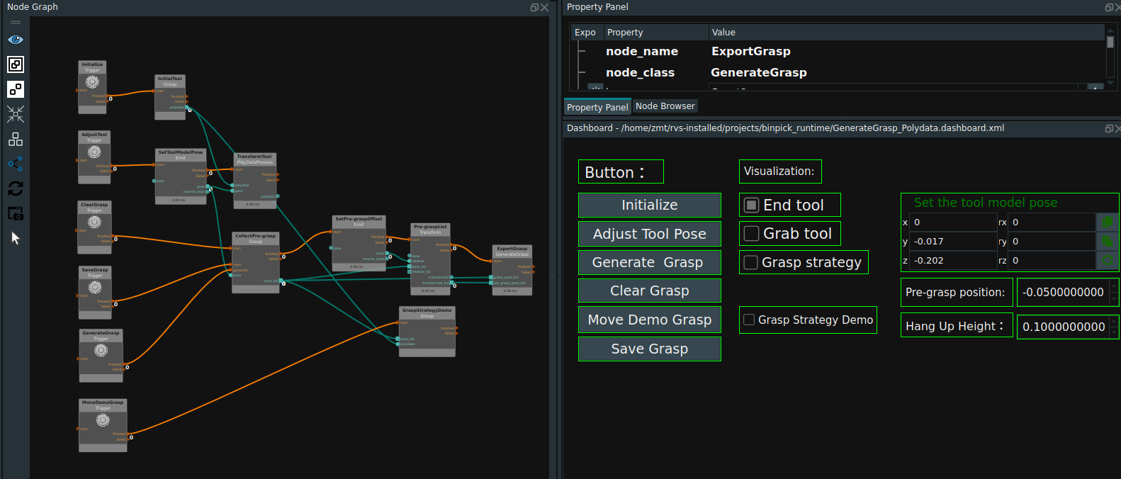
Add tool model and target model.
Double click to open
InitialToolGroup,TheGenerateOriginPosenode creates the origin pose of the coordinate system and displays it.LoadModelPointCloudLoads the upper surface point cloud of the target object.LoadObjectModelLoad target model,LoadToolModelLoad tool model. As shown in the following picture.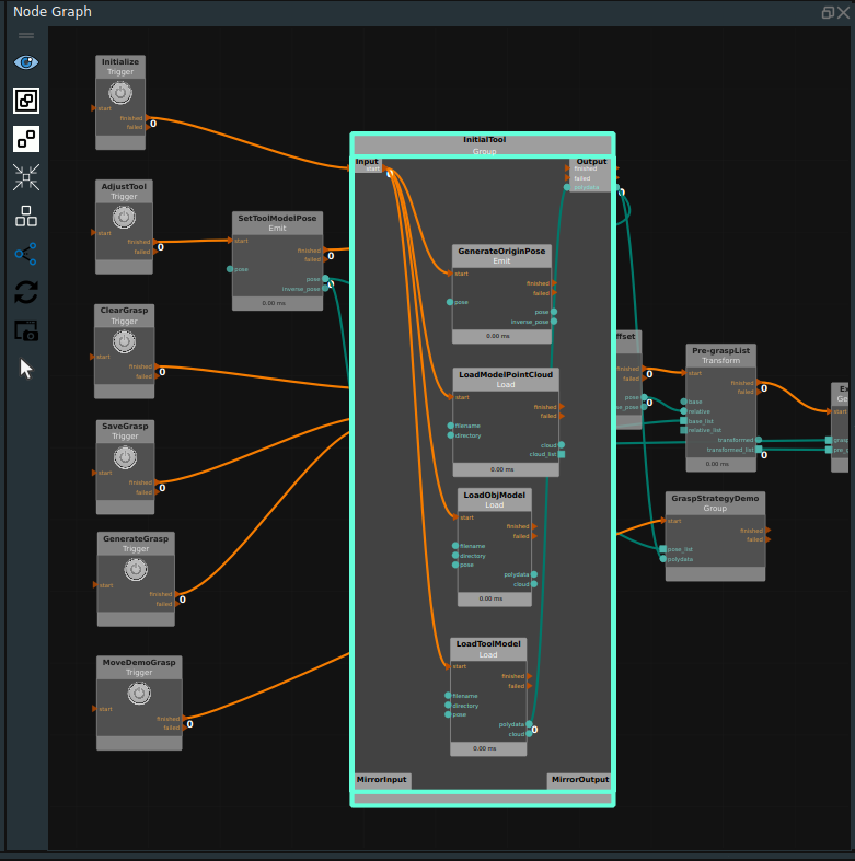
Click the RVS Run button.
Initialize the target model and tool model.
Click the
Initializebutton in the dashboard to display the origin of the coordinate system and the model in the 3D view. Check theEnd toolcheck box to display the initial tool model in the 3D view.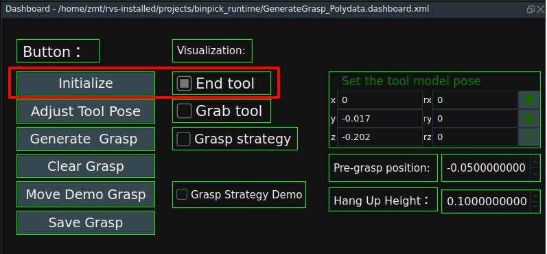
After initialization, the 3D view appears as follows:
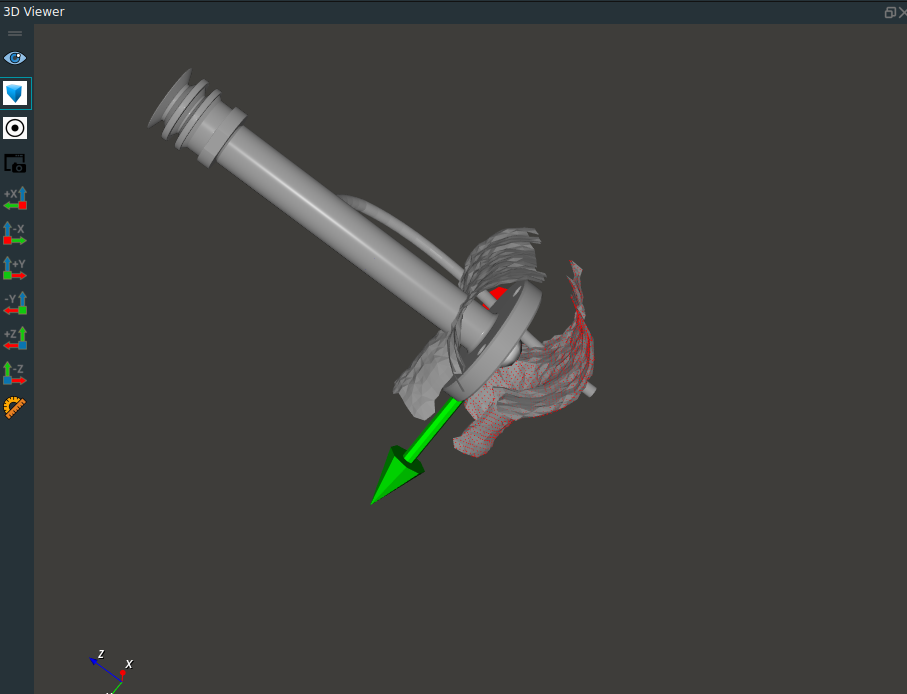
Move the tool model to the corresponding grasp point.
Click the
Adjust Tool Posebutton in the dashboard.Set the
Set the tool posecontrol parameters in the dashboard.After setting parameters.Click theSet the tool posebutton again, check theGrab toolcheckbox to open the grasp tool model visualization,Observe whether the tool model moves to the corresponding grasp position.Repeat until the tool model moves to the grasp point.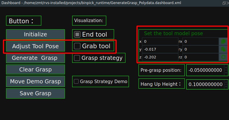
The tool model is moved to the grasp point as shown below:
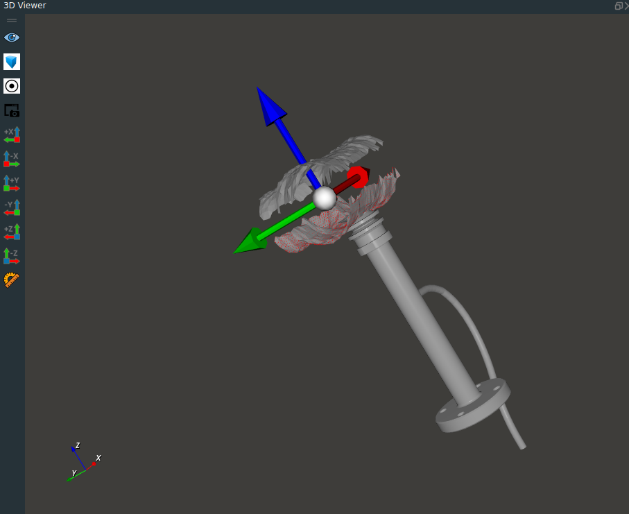
Set the pre-grab position and grab raise position. See section 1.1.7 for this definition.
Pre-grasp position:Here the parameter is the body coordinate system with respect to the target object.Hang Up Height:Here the parameters are relative to the base coordinate system of the robot.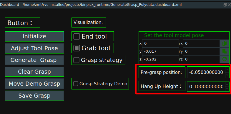
Set the sample generation mode of the grasping strategy.
Set in the
GenerateSamplePosenode in theCollectPre-graspGroup. In this case, the Z-axis is rotated 12 times in place to generate a grasp strategy.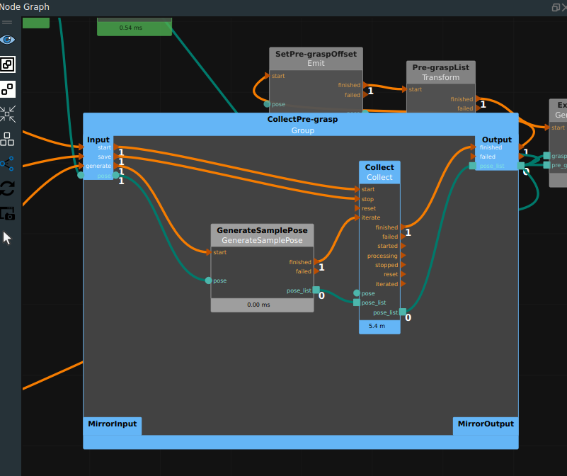
Generate the grasp strategy and move the display grasp strategy.
Click the
Generate Graspbutton in the dashboard to generate the grasp strategy. CheckGrasp Strategyto display the generated grasp strategy in the 3D view.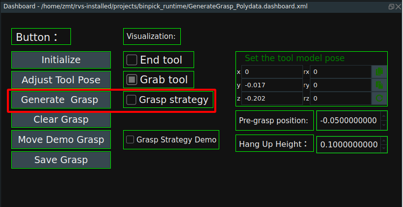
The 3D view displays the following:
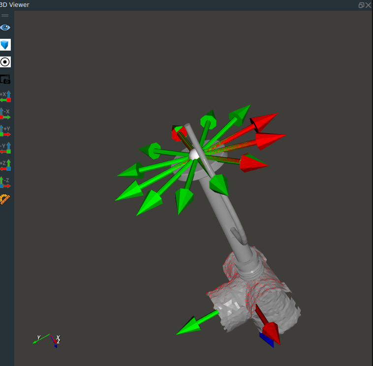
If the generated grasping strategy is not correct, you can clear it by clicking the
Clear Graspbutton in the dashboard.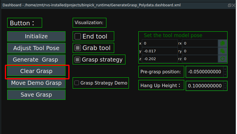
Click the
Move Demo Graspbutton in the dashnboard to move the display garsp strategy. CheckGrasp Strategy Demofor grasp strategy demo in 3D view.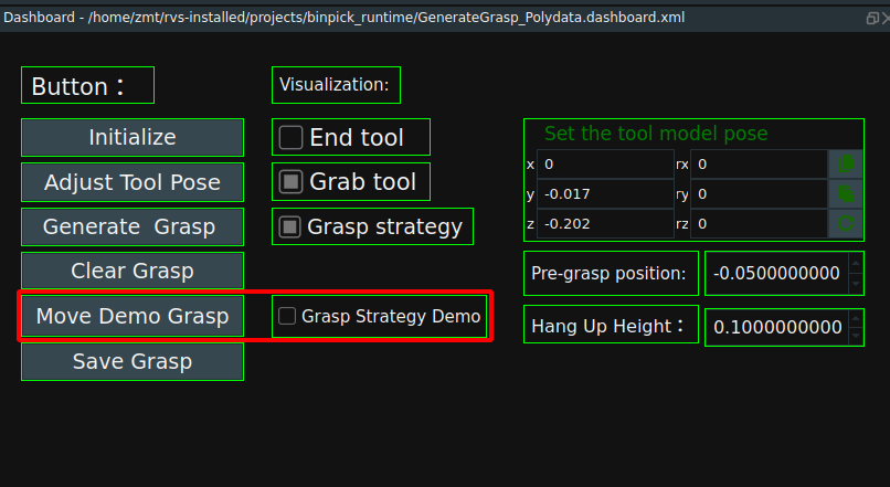
Save the grasp strategy.
In the
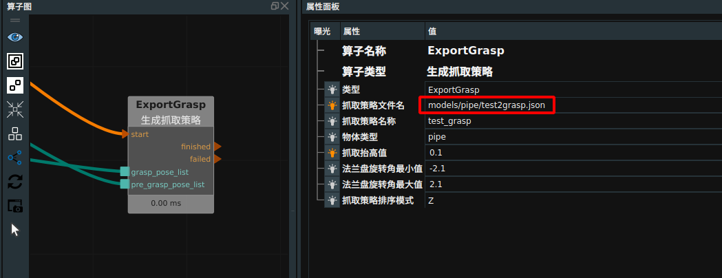
ExportGraspnode, you can set the location and name where the grasp is saved. Click theSave Graspbutton in the dashboard to save the grasp strategy.Note:The name of the grasping strategy can only be named grasp.json to be used by the scene resource identification.
Note:The name of the deep box saved in this case is test1grasp.json, and the name of the grasping strategy used in the later case project is grasp. Because this case is for teaching use, to avoid learners in the process of use due to improper operation and subsequent project problems.
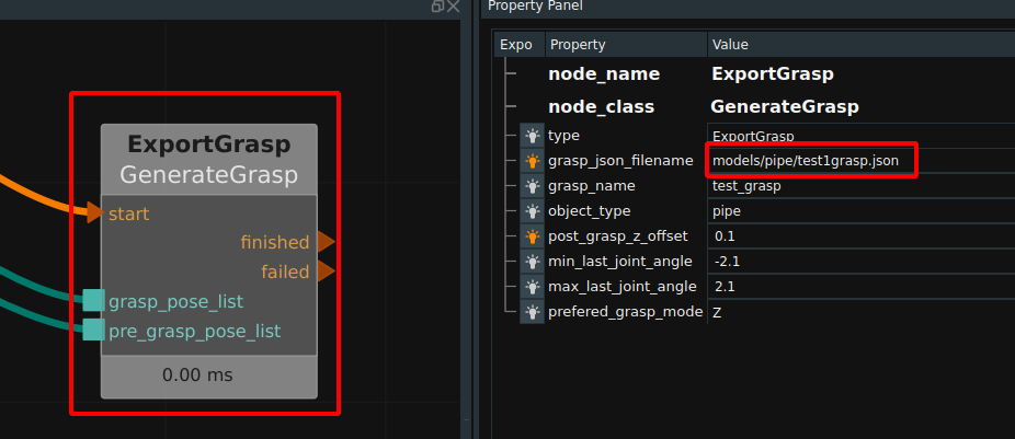
The end coordinate system of the tool and the point cloud on the surface of the target generate grasping strategy.
Operation process:
Load GenerateGrasp_cloud.xml as shown in the following figure.
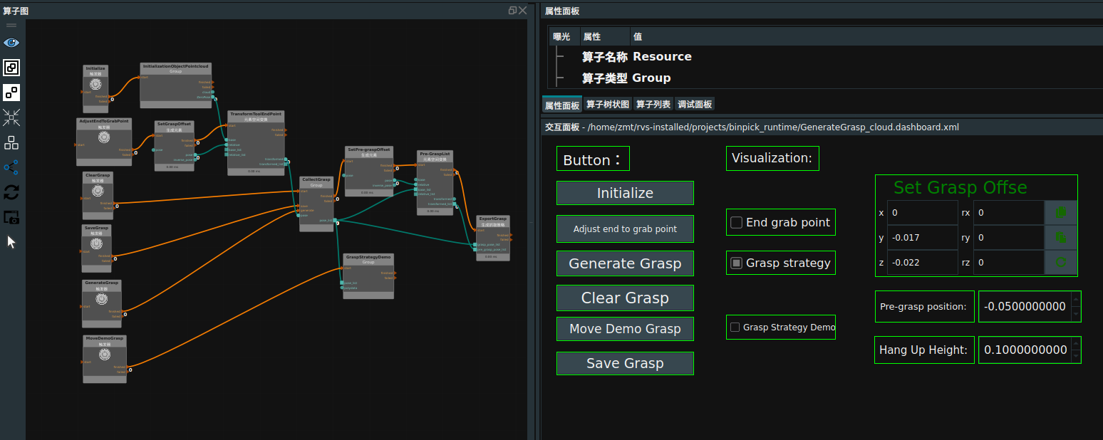
Adds a surface point cloud on the target object
Double-click to open the
InitializationObjectPointcloudGroup, whereGenerateOriginPosecreates the origin of the coordinate system for easy viewing, andLoadModelPointCloudloads the surface point cloud of the target object. As shown in the following picture.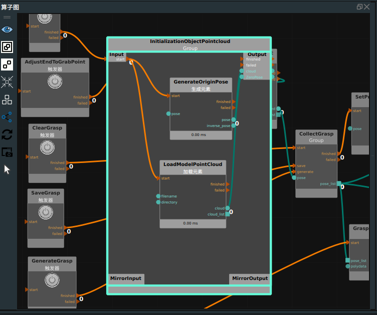
Click the RVS Run button.
Initializes the surface point cloud on the target.
Click the
Initializebutton in the dashboard to display the origin of the coordinate system and point cloud in the 3D view.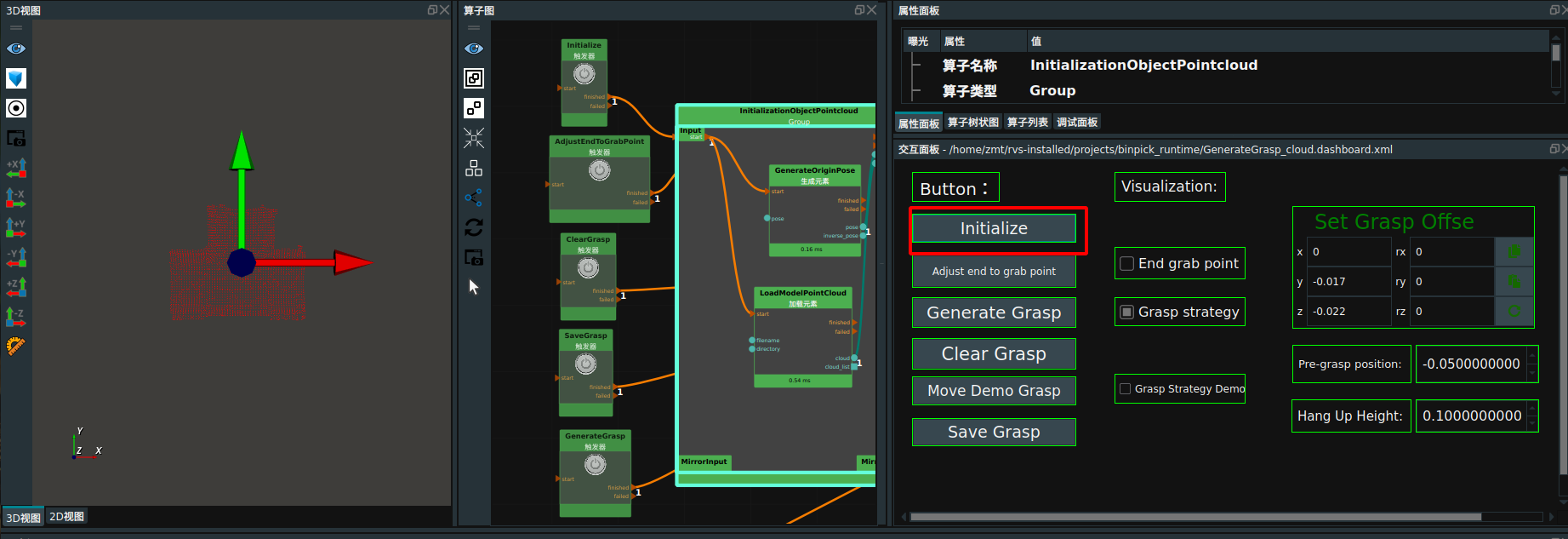
Move the end point pose to the grasp point.
Click the
Adjust end to grab pointbutton in the dashboard.Set the parameters in the
Set Grasp Offsewidget on the dashboard. After setting parameters.ClickAdjust end to grab pointbutton again,CheckEnd grab pointto observe whether the end point pose moves to the corresponding grasp position.Repeat until the end point pose moves to the grasp point.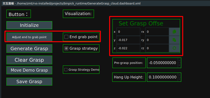
The end point pose is moved to the grasp point as shown below:
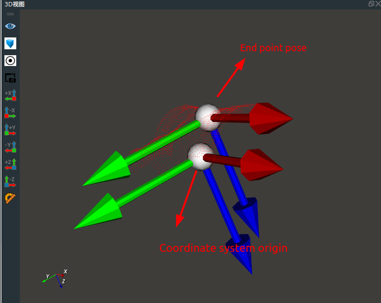
Set the pre-grasp position and grasp elevation position. See section 1.1.7 for this definition.
Pre-grasp position:Here the parameter is the body coordinate system with respect to the target object.Hang Up Height:The parameters here are relative to the base coordinate system of the robot.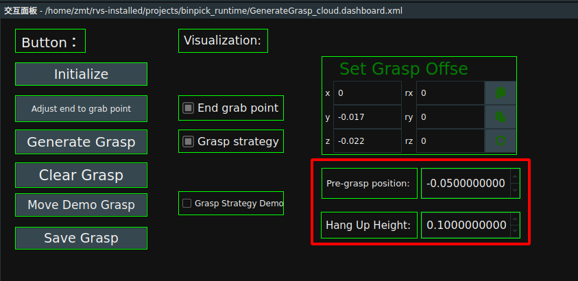
Set the sample generation mode of the grasping strategy.
Set it in the
GenerateSamplePosenode in theCollectGraspGroup.In this case, rotate around the z-axis 12 times in place to generate a grasping strategy.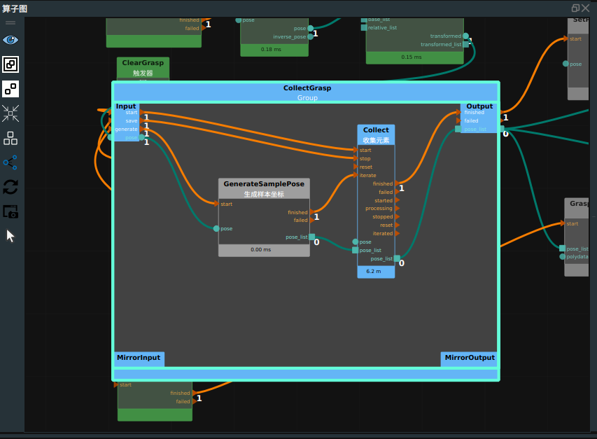
Generate the grasp strategy and move the display grasp strategy.
Click the
Generate Graspbutton in the dashboard to generate the grasping strategy, and check theGrasp Strategy Democheckbox to display the generated grasping strategy in the 3D view. As shown in the following picture.
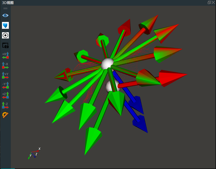
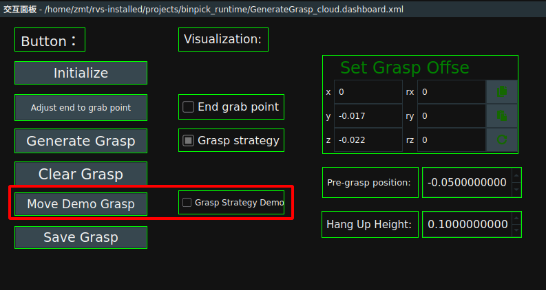
If the generated grasping strategy is not correct, click the
Clear Graspbutton in the dashboard to clear the grasping strategy.Click the
Move Demo Graspbutton in the dashboard to move the grasping strategy. Check theGrasp Strategy Democheckbox to open a visualization showing the grasp strategy.
Save the grasping strategy.
In the
ExportGraspnode, you can set the location and name of the grab.Click theSaveGraspbutton in the dashboard to save the grab strategy.Note:The name of the deep box saved in this case is test2grasp.json, and the name of the grasp strategy used in the later case project is grasp.json.Because this case is for teaching use, to avoid learners in the process of use due to improper operation and subsequent project problems.
