Percipio Viewer supports modifying the IP address of network cameras to static or dynamic IP addresses. To ensure Percipio Viewer can successfully open the camera, it is recommended to check the camera’s IP address first to ensure it is on the same subnet as the host PC’s IP address.
Prerequisites
Before setting a static IP address, ensure the host PC’s IP address is on the target subnet.
If the camera is currently connected to the software, disconnect it before setting the IP.
Procedure
On the Camera List page, click to refresh the camera list.
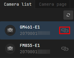
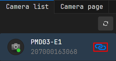
Click the serial number of the target camera to select it.
If there is no icon next to the camera serial number, it means the camera cannot be connected currently. Click the serial number and check the status in the camera details to troubleshoot the connection issue.
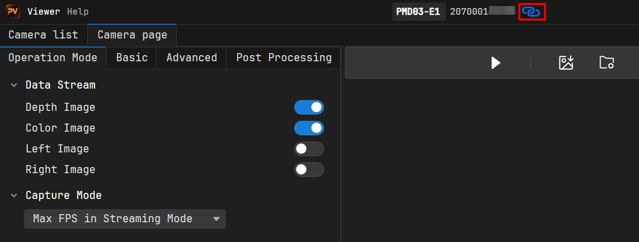
After connecting, the interface automatically switches to the Camera Page. Click at the top of the page to disconnect.
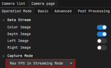
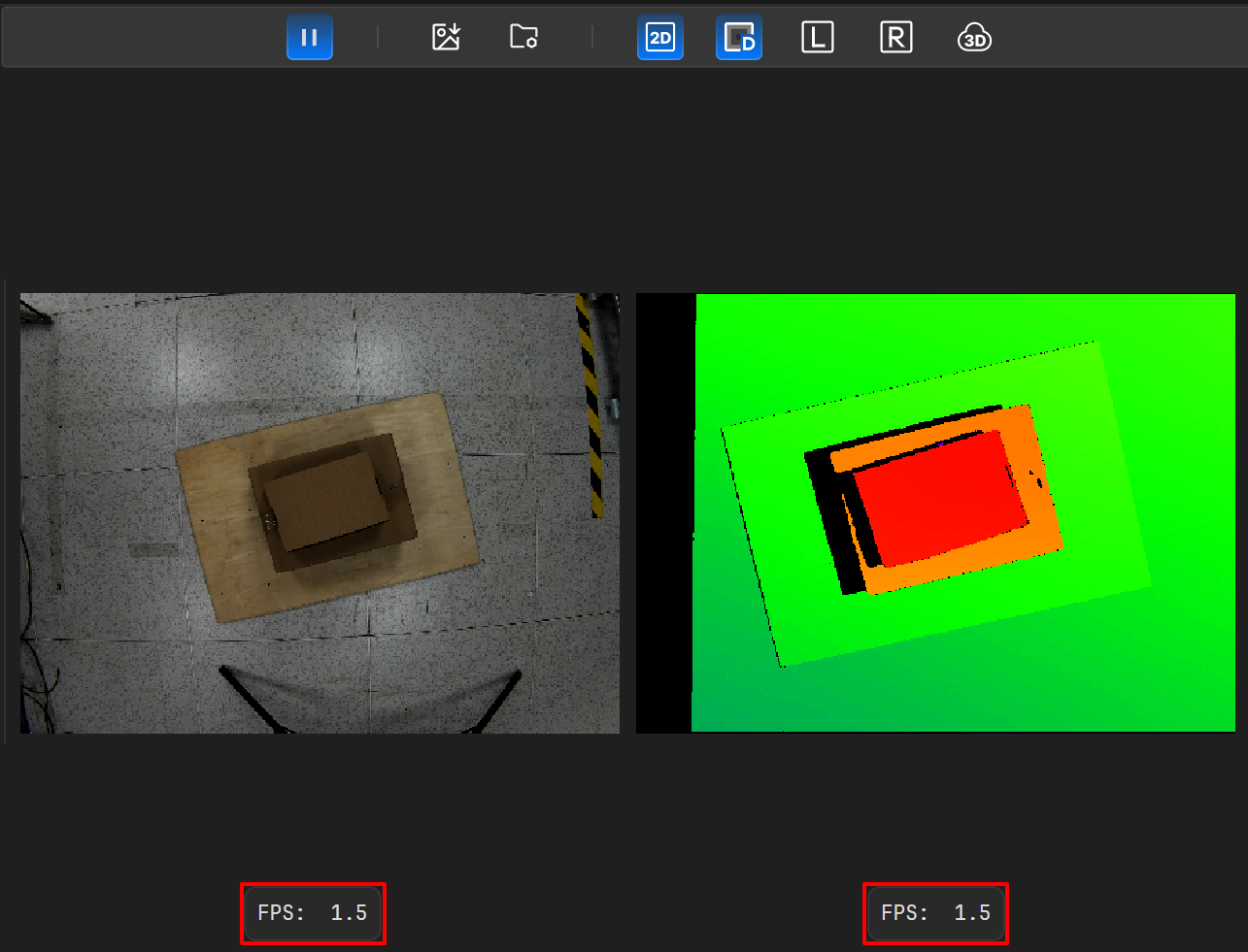
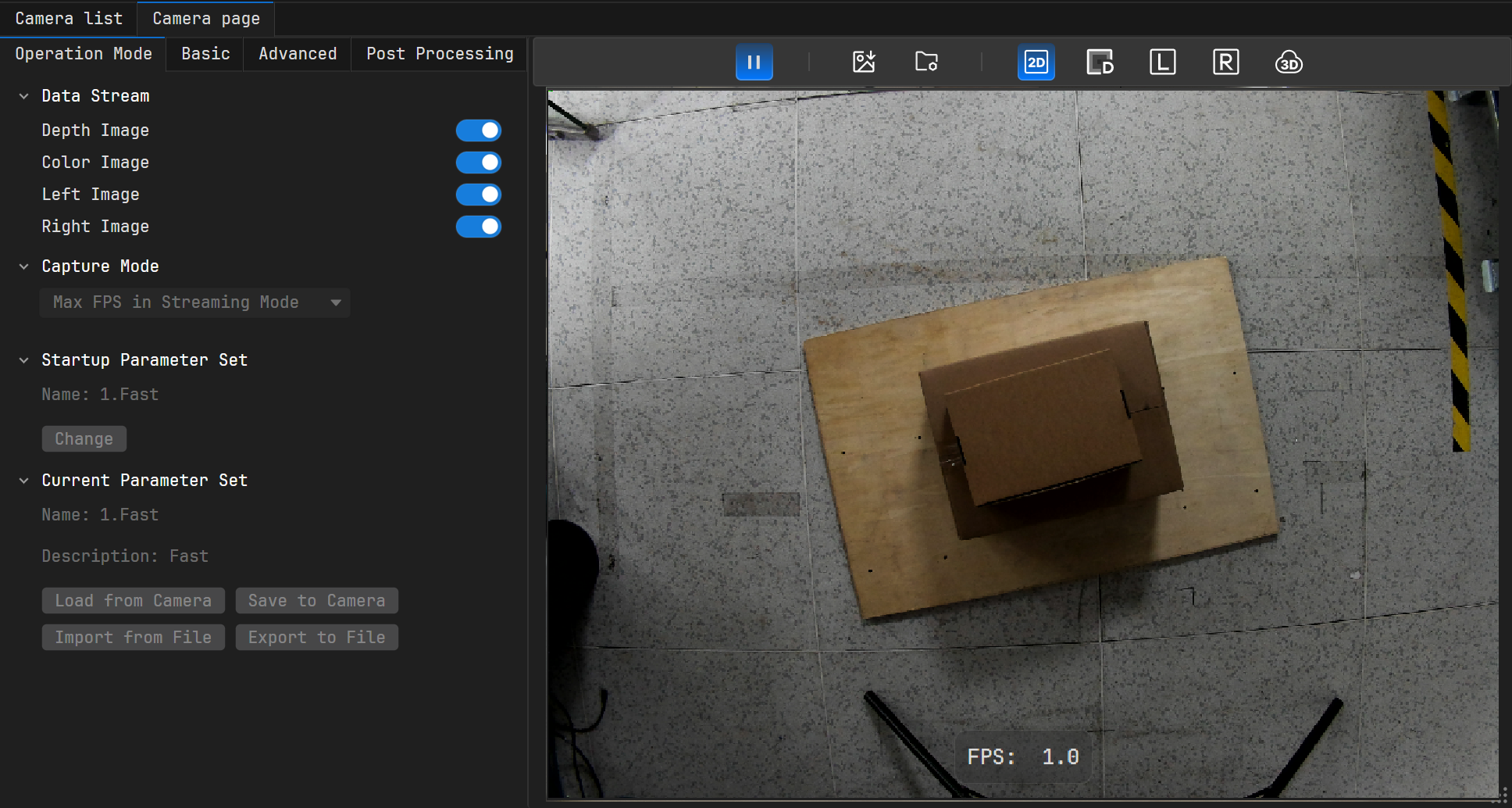
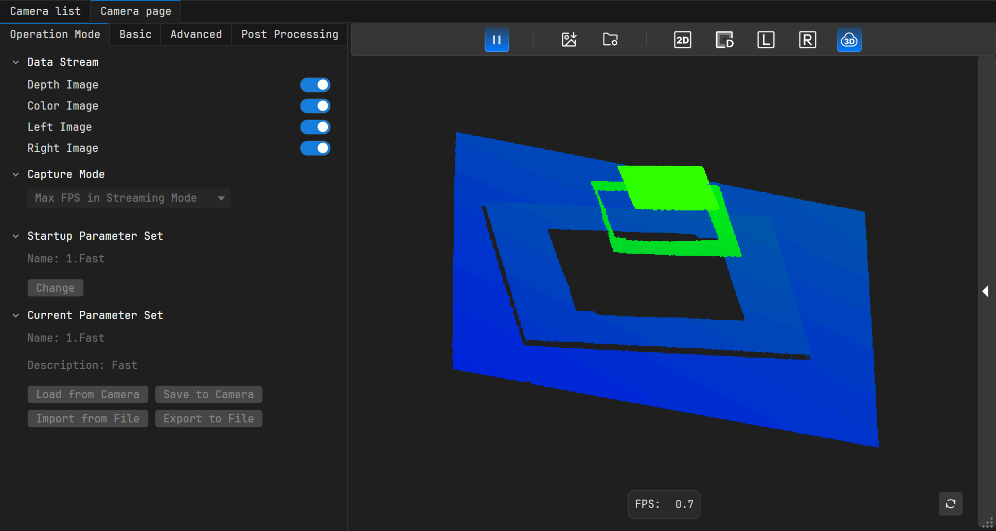
In this mode, the software will continuously output enabled data streams at the set frame rate. If the set frame rate is higher than the system’s maximum output frame rate under the current configuration, images will be output at the system’s maximum frame rate.
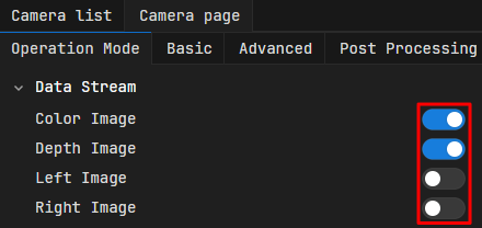
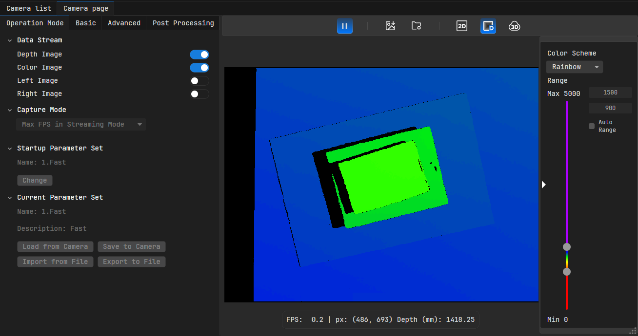
In the Data Stream field of the Operation Mode page, enable the corresponding data streams, such as “Depth Image” and “Color Image”.
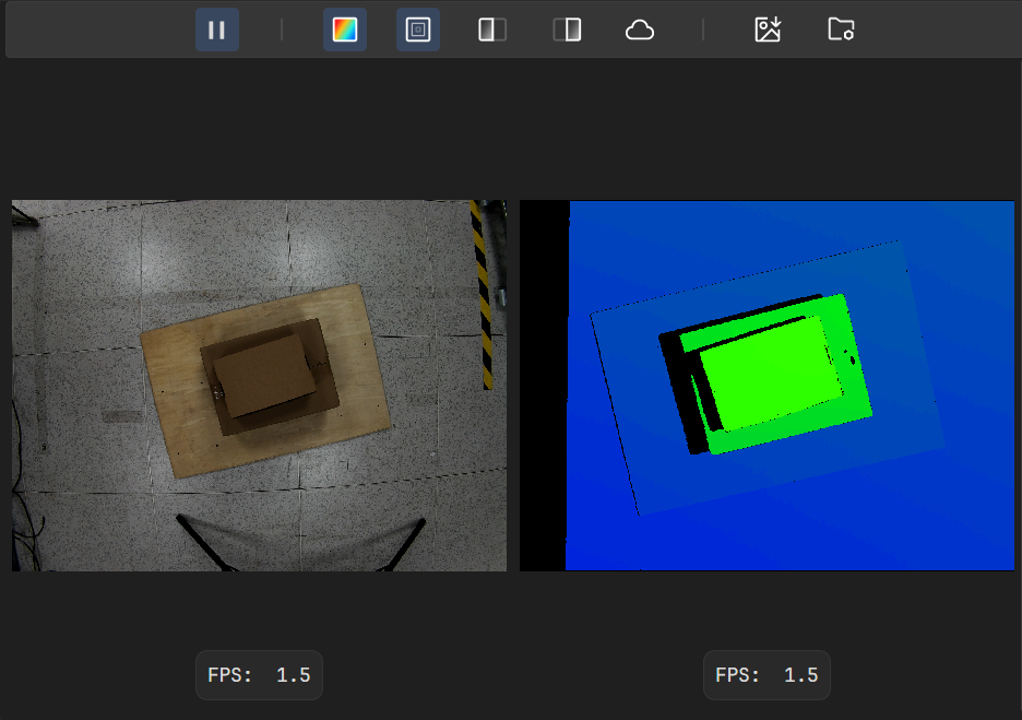
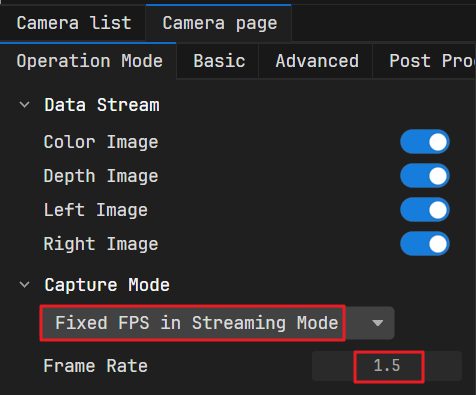
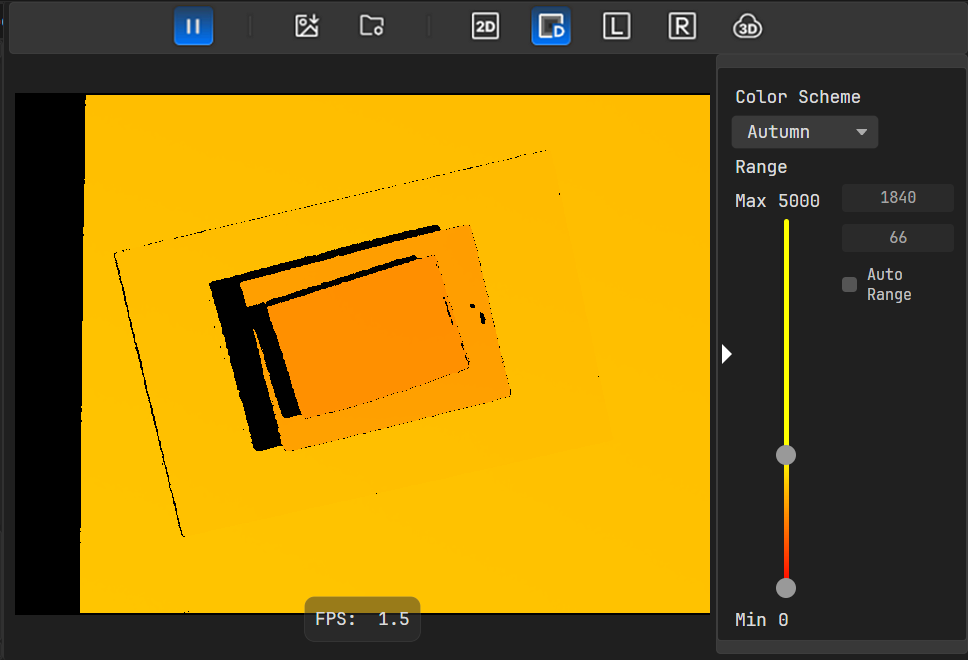
Please note that even if the software outputs images at the set frame rate, the actual frame rate may still fluctuate slightly around the set value. For example, the set frame rate is 1.5 fps, but the output frame rate shown above is 1.4 fps.
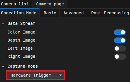
In this mode, the camera accepts external hardware trigger signals and outputs images.
Complete the hardware wiring to ensure the camera can receive external hardware trigger signals. For specific wiring methods, refer to Hardware Trigger Connection Methods.
In the Data Stream field of the Operation Mode page, enable the corresponding data streams, such as “Depth Image” and “Color Image”.
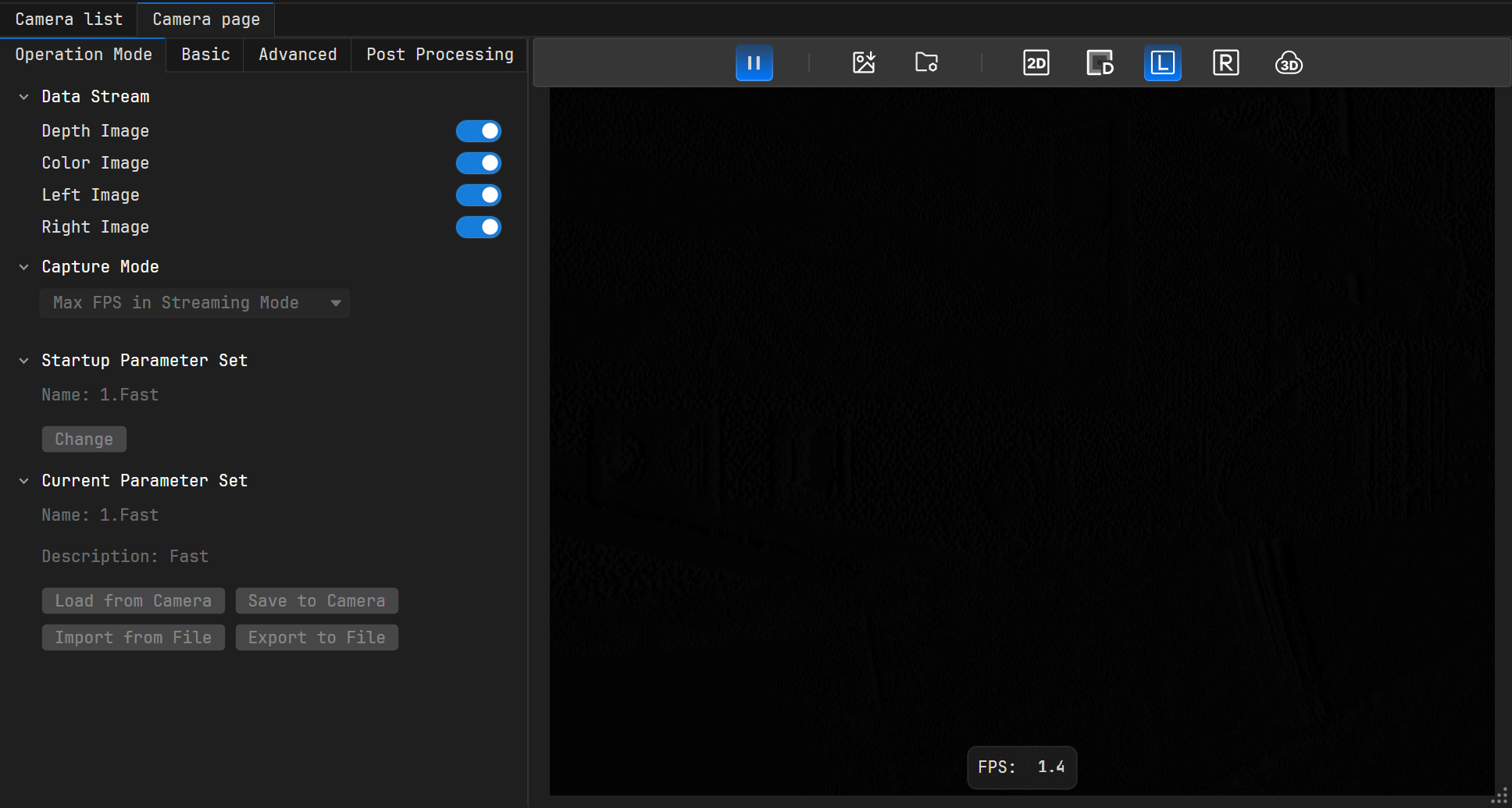
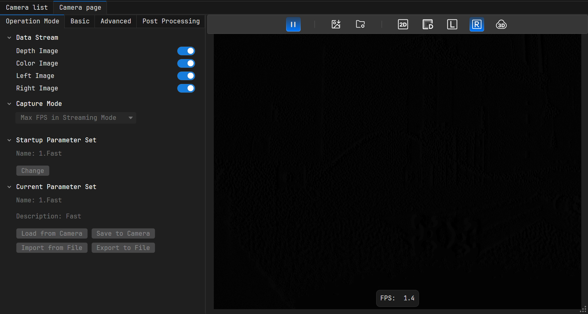
Enable the right image data stream, click , then click above the image capture area to view the right image. Click again to close the right image view.
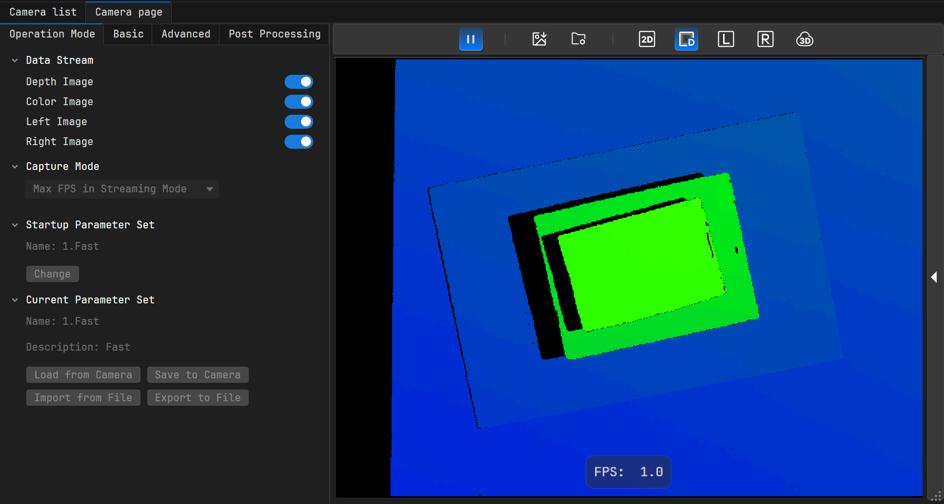
When the depth image display is on, you can click on the right side of the image capture area to bring up the depth map rendering area and switch between different color schemes under the “Color Scheme” option.
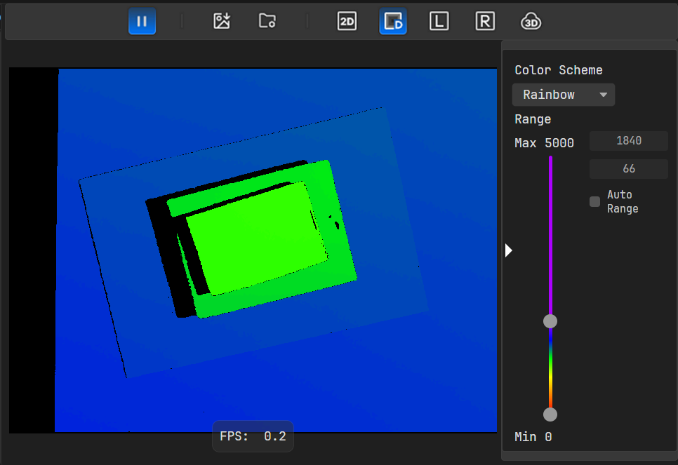
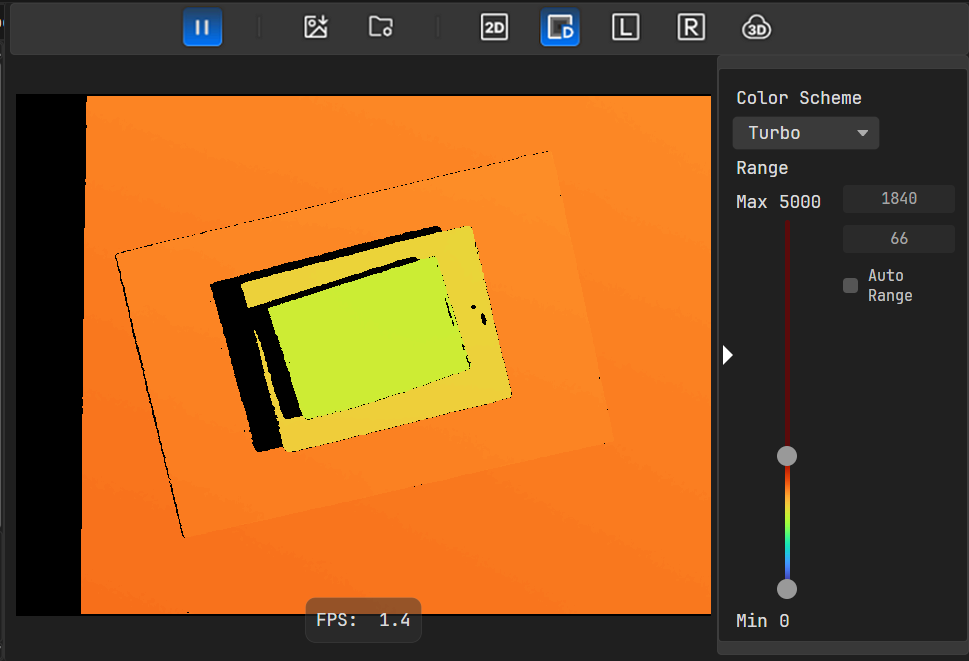
The software currently supports the following rendering color schemes: Rainbow, Autumn, Turbo. The rendering effect differs when different schemes are selected.
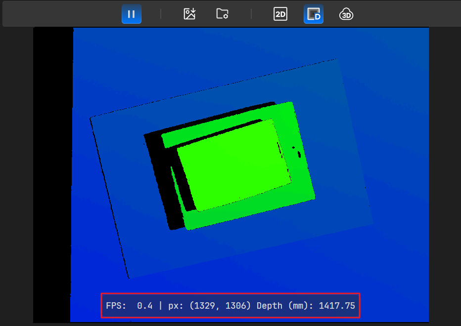
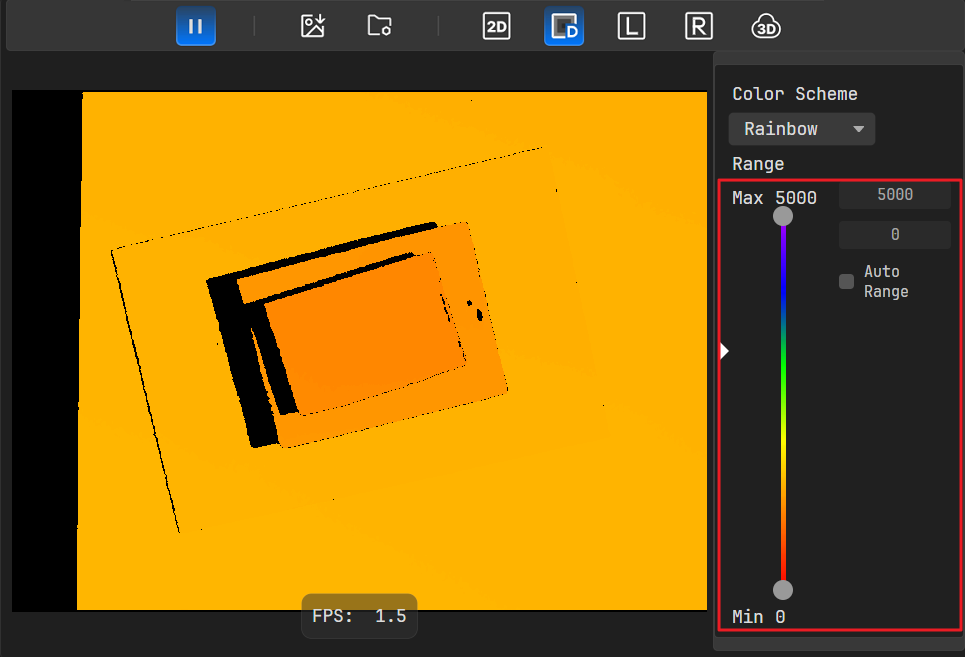
The depth map supports dynamic rendering range adjustment. When the depth image display is on, you can click on the right side of the image capture area to bring up the depth map rendering area.
When the depth value is between the Min (minimum) and Max (maximum), the color gradient is evenly distributed; pixels with depth values less than the minimum are displayed in red, and pixels with depth values greater than the maximum are displayed in purple. By optimizing the color mapping for the target depth interval, the discernibility of depth details can be enhanced.
Specific adjustment methods are as follows:
When “Auto Range” is checked, the system automatically determines the maximum and minimum values used for rendering based on the statistical results of the depth map.
When “Auto Range” is not checked, you can adjust Min and Max of the rendering depth using the sliders or set them via the input fields.
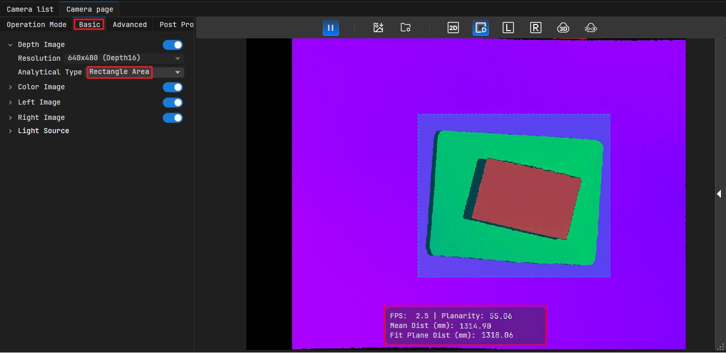
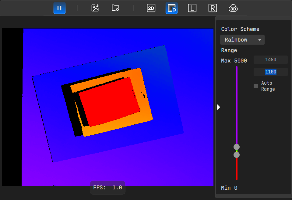
When the target object is concentrated in the 1100-1450 mm range:
Using the default rendering range (0-5000 mm): The color gradient is gentle, making details difficult to distinguish.
Narrowing the range to 1100-1450 mm: As shown in the right image below, color contrast is vivid, and depth differences of the object can be clearly distinguished.
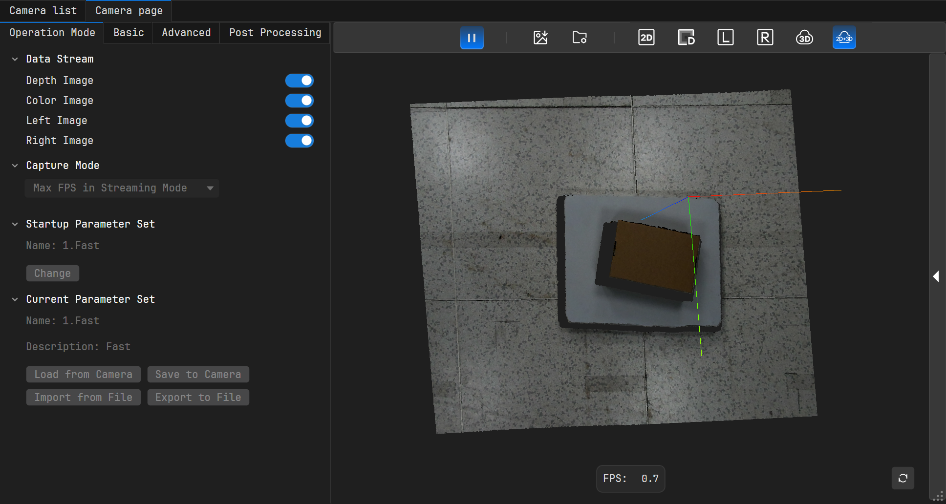
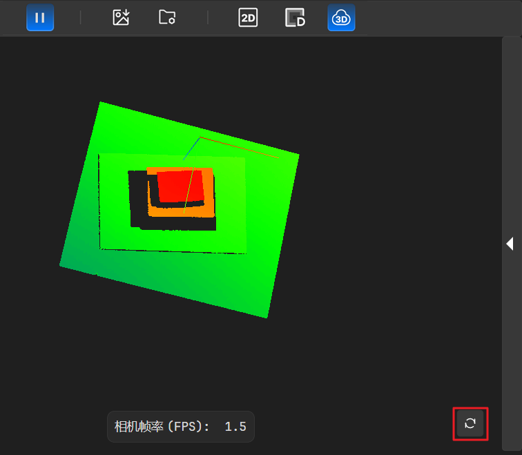
When the point cloud view is displayed, you can perform the following operations:
Zoom: Place the mouse on the point cloud view and scroll the mouse wheel.
Rotate: Hold down the left mouse button and drag.
Pan: Hold down the right mouse button and drag.
Reset: Press the “R” key on the keyboard or click the icon in the lower right corner of the point cloud view to restore the point cloud to its initial position.
Percipio Viewer supports saving image data to the local drive according to the set save count and capacity limits. Color images, depth images, left images, right images, and point cloud data can be saved simultaneously.
Procedure
Enable the data streams corresponding to the data you want to save.
Click to open the Image Save Settings dialog.
In the “Save Path” field, enter a folder path or click to select a directory for storing data. Then, click Confirm. If the specified path does not exist, the system will automatically create the folder.
If no prompt appears, the path setting was successful. Images will be saved to the target path with the naming convention “Type_Date-Timestamp”.
Set the “Continuous Save Count”, i.e., the number of frames to save.
Set the “Capacity Limit” for the selected folder. Setting it to 0 means there is no limit.
Note
The software’s continuous image saving function is subject to two limits: continuous save count and storage capacity limit. Saving will stop immediately when either condition reaches its set value first.
Check the desired storage object(s), supporting single or multiple selections.
The correspondence between Storage Object Options and Saved Data is as follows:
Checked Storage Object
Saved Data
Save Color Image
Color image (PNG)
Color component intrinsic/extrinsic parameters and distortion matrix (TXT)
Save Depth Image
Raw depth image (PNG)
Rendered depth image (PNG)
Depth component intrinsic/extrinsic parameters and distortion matrix (TXT)
Save Left/Right Image
Left image (PNG)
Right image (PNG)
Left component intrinsic/extrinsic parameters and distortion matrix (TXT)
Right component intrinsic/extrinsic parameters and distortion matrix (TXT)
Save Point Cloud
Point cloud (PLY or PCD)
Depth component intrinsic/extrinsic parameters and distortion matrix (TXT)
Note
Point Cloud Format Explanation:
This software supports saving point clouds in PLY format or PCD format. Users can choose based on the format required for subsequent point cloud processing.
PLY: Binary format, storing spatial coordinates x, y, z, color r, g, b, etc., for each point in the point cloud.
PCD: Binary format, designed for efficient use with the Point Cloud Library (PCL).
Click Confirm.
Click to start image capture (you can also configure image save settings after the camera has started capturing). Then click . The button will highlight, indicating saving is in progress. If the highlighting disappears, it indicates saving has ended.
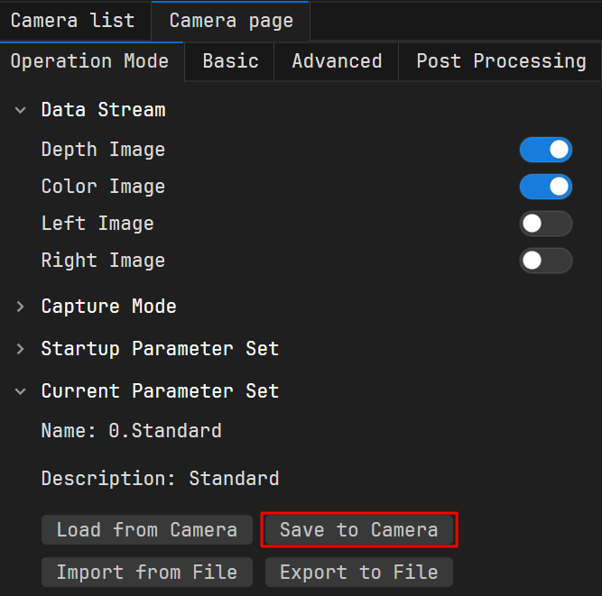
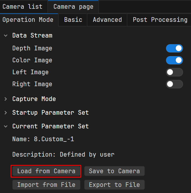
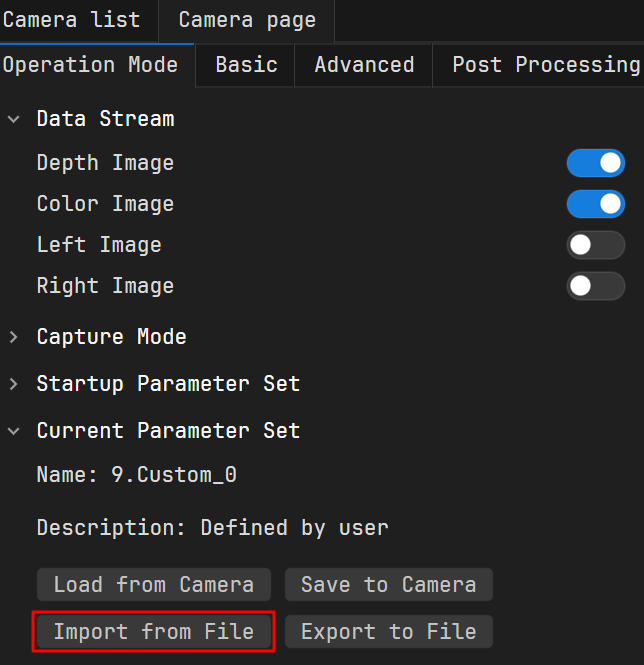
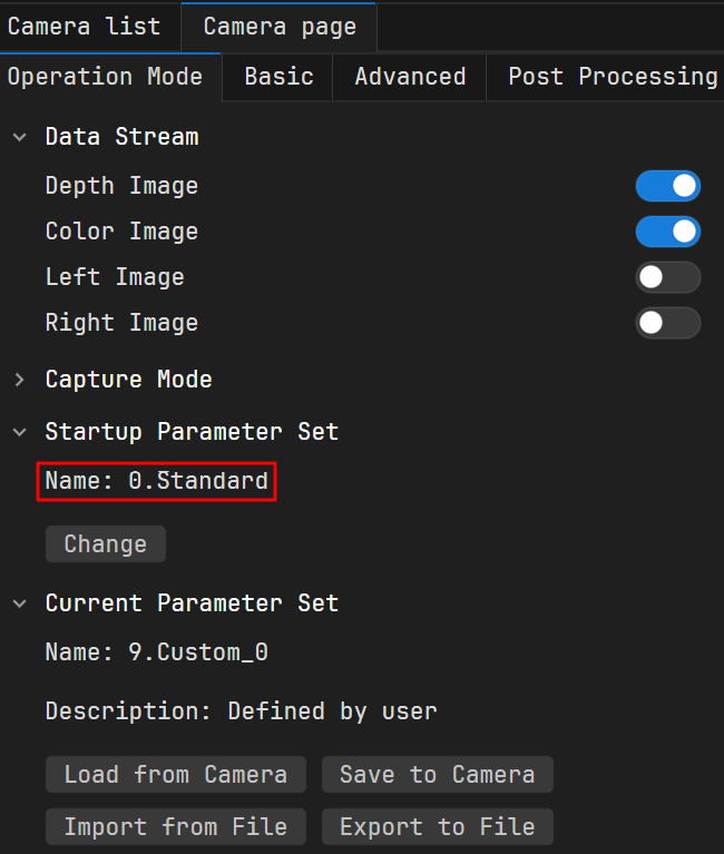
Parameter Sets (User Configurations) allow saving customized parameter settings to the camera or to local for different application scenarios. When switching between scenarios, loading the corresponding parameter set enables quick parameter adjustment.
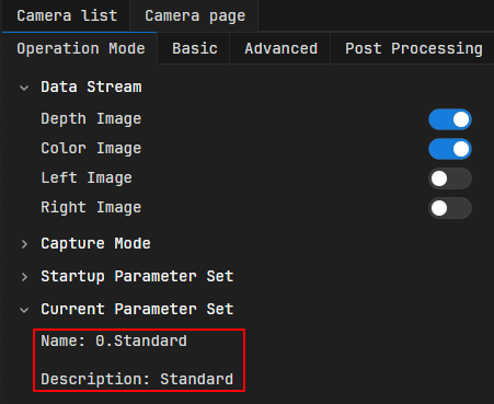
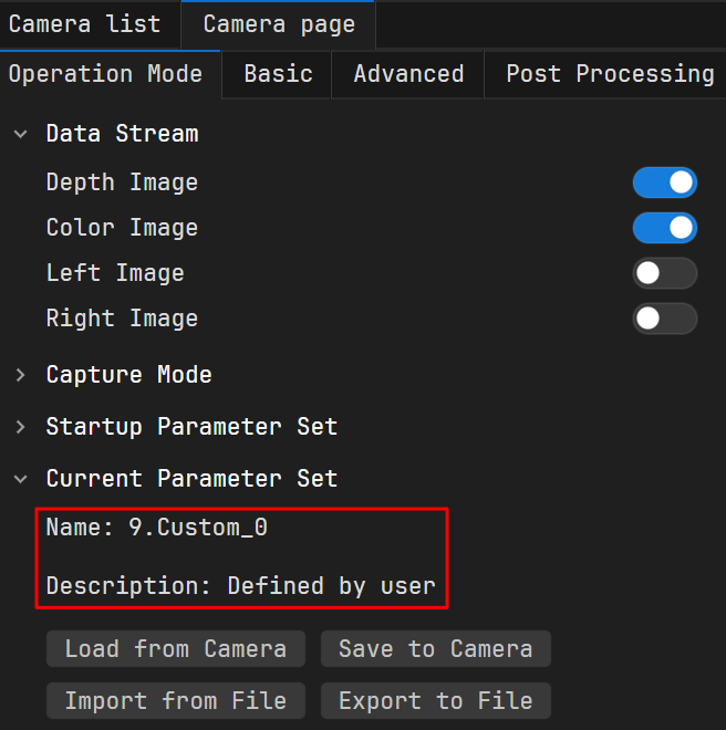
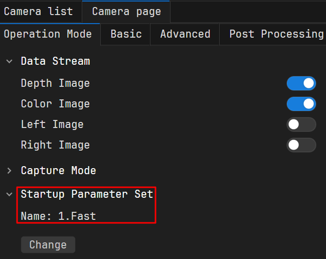
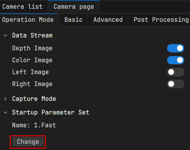
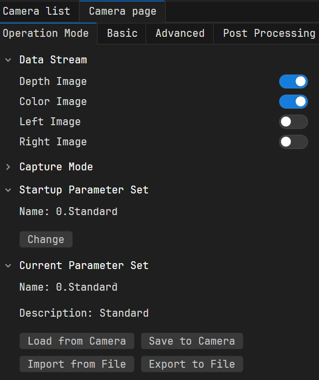
On the Camera Page, the Current Parameter Set field displays the active parameter set information: “Name” Shows the name of the currently active parameter set; “Description” provides explanatory details about the parameter set.
As shown below, the current parameter set name is “0.Standard”, and the description is “Standard”.
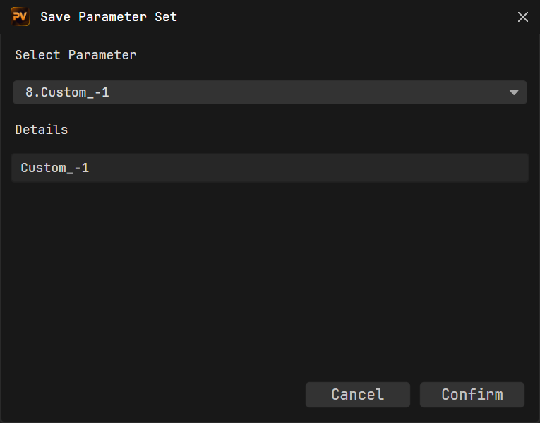
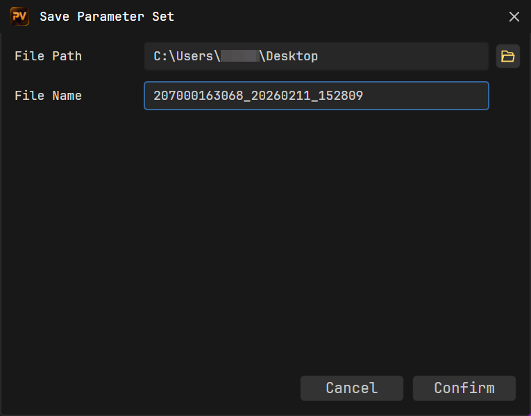
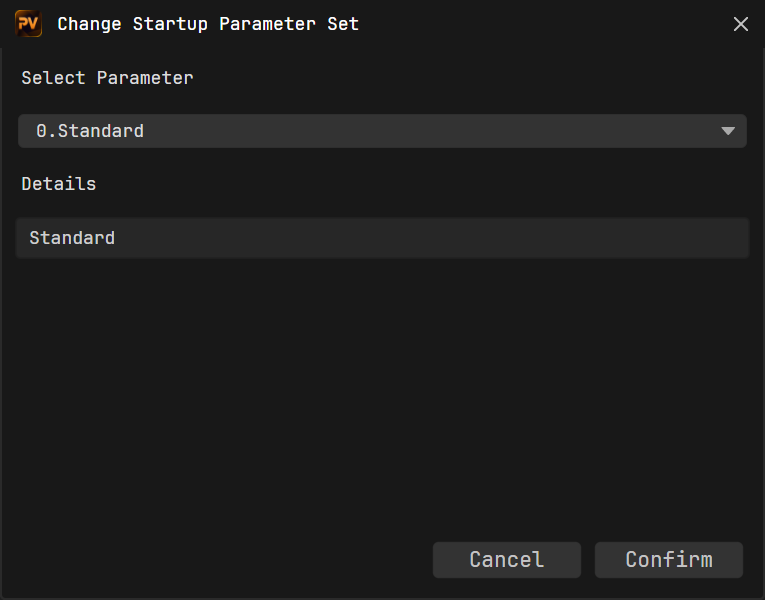
In the popped-up Save Parameter Set dialog, select a parameter set and enter information in the “Details” field if needed. The final saved user set name will be a combination of “Order Number + Details”, such as “8.test”.
Note
If the “Details” field is left blank, the software will automatically use the default name “Default description” as the details for that user set.
After the camera is powered off and restarted, open it with Viewer. The “Current Parameter Set” updates to the set parameter set, and the camera parameters synchronize with the new values.
 to refresh the camera list.
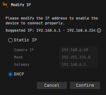
 .
.
 in the image capture area to start capturing. Then click
  and
and  to turn the color and depth views on/off.
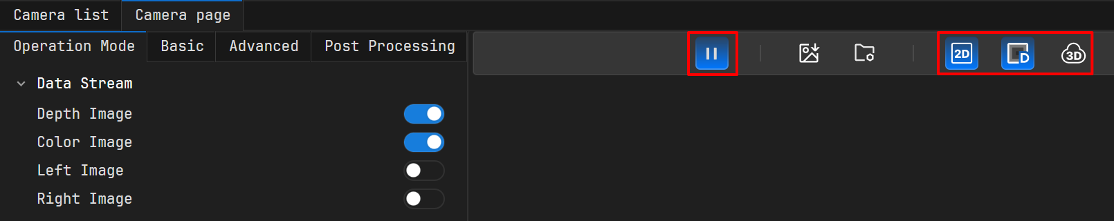
 will appear next to it. Then click
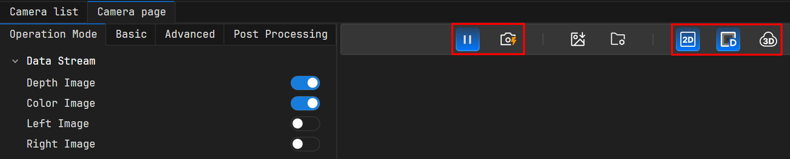
 to open the Image Save Settings dialog.
 to select a directory for storing data. Then, click
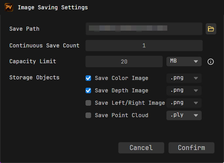
 . The button will highlight, indicating saving is in progress. If the highlighting disappears, it indicates saving has ended.