Get Started with Camera
Unbox
When you receive the package, refer to the Item List inside to check if all items and accessories are present and undamaged. In case of any missing or damaged items, contact Percipio’s technical support promptly.
Note
The following list is for reference only. Please refer to the actual Item List in the package.
Name |
Image |
|---|---|
3D Camera |
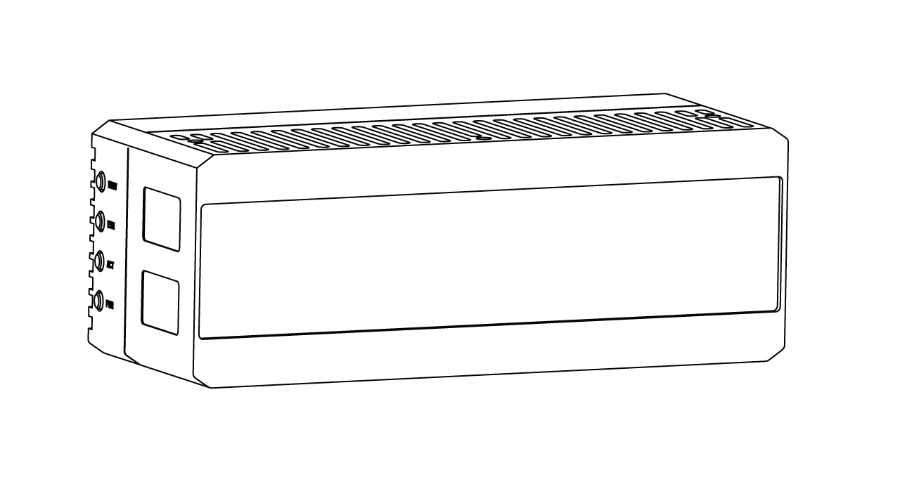
|
User Manual (E-Manual) |

|
Gigabit Ethernet Cable |

|
DC Power Supply and Trigger Cable |

|
Connect Cables
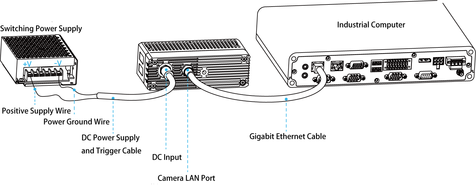
As shown in the figure below, connect the camera to the power supply and the industrial PC.
Connect to Power Supply
The figure above utilizes a DC power supply to provide power to the camera. Connect the Power Positive Wire and Power Ground Wire from the open end of the Power & Trigger cable to an external DC power supply, and connect the other end to the camera’s DC power connector. For descriptions of the wire sequence in the DC power cable, refer to the Product Specifications of the corresponding camera model .
For more power supply methods, refer to Hardware Connections .
Connect to Network
The figure above shows a direct connection between the camera and the industrial host computer. Connect the RJ45 end of the Gigabit Ethernet cable to the network port of the industrial host computer, and connect the other end to the camera’s LAN network interface.
For more network connection methods, refer to Hardware Connections .
Set Up USB Camera
For Windows users, download and install the USB driver before using a USB camera.
Download the USB Driver
Download link: https://res1.percipio.xyz/usbdriver/usb_driver.zip
Installation Steps (GM461-U2, GM463-U2)
Extract
usb_driver.zip.Double-click
install.bat.
Installation Steps (Legacy USB Cameras)
Connect the Percipio depth camera to the Windows PC with a USB cable. Right-click Start in the lower-left corner of the desktop, then click Device Manager in the Start menu. In Device Manager, you can find an unrecognized USB device named
PERCIPIO DEVICEEE, as shown below:
Unrecognized USB device
Right-click the device and select Update driver. According to the Windows version on the PC, choose the driver under the “driver” path and follow the system prompts to complete the installation.

Camport3 device driver
After the driver is installed successfully, the Percipio Device appears in Device Manager.
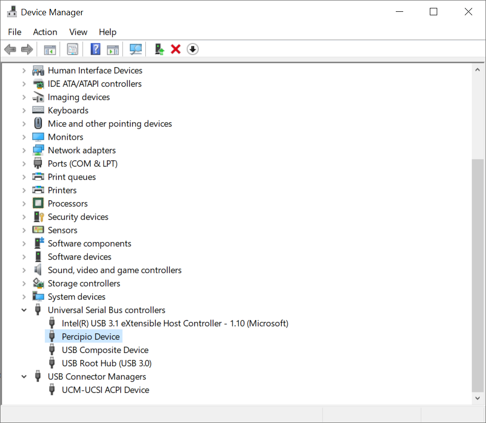
Percipio Device
For Linux users, install the USB driver and configure access permissions before using a USB camera.
Install the USB Driver
sudo apt-get install libusb-1.0-0-dev
Configure Access Permissions for USB Devices
On Linux systems, root privileges are required by default to access USB devices directly. Therefore, before accessing a Percipio USB camera, non-root users need to create a udev rule and modify the access permissions for the USB device.
The steps are as follows:
Create a rule file with the
.rulesextension in the “etc/udev/rules.d” directory, for example, 88-tyusb.rules.Note
The rule file name must start with a number (0 to 99). A larger number indicates a higher priority.
sudo nano /etc/udev/rules.d/88-tyusb.rules
Add the following rules to the file. These rules add the USB device to the tofu user group.
SUBSYSTEM== "usb",ATTRS{idProduct}=="1003",ATTRS{idVendor}=="04b4",GROUP="tofu",MODE="0666"
SUBSYSTEM== "usb",ATTRS{idProduct}=="1004",ATTRS{idVendor}=="04b4",GROUP="tofu",MODE="0667"
Restart the PC to obtain access to the USB camera.
Use Image Viewer Software
Download Software
Click the link to download ![]() .
.
Install Software
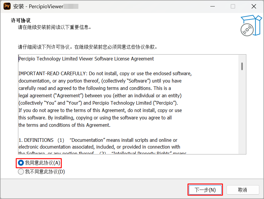
After downloading the installer, double-click
PercipioViewer-X.X.X-x64-Setup.exe.Select “I accept the agreement” and click Next.
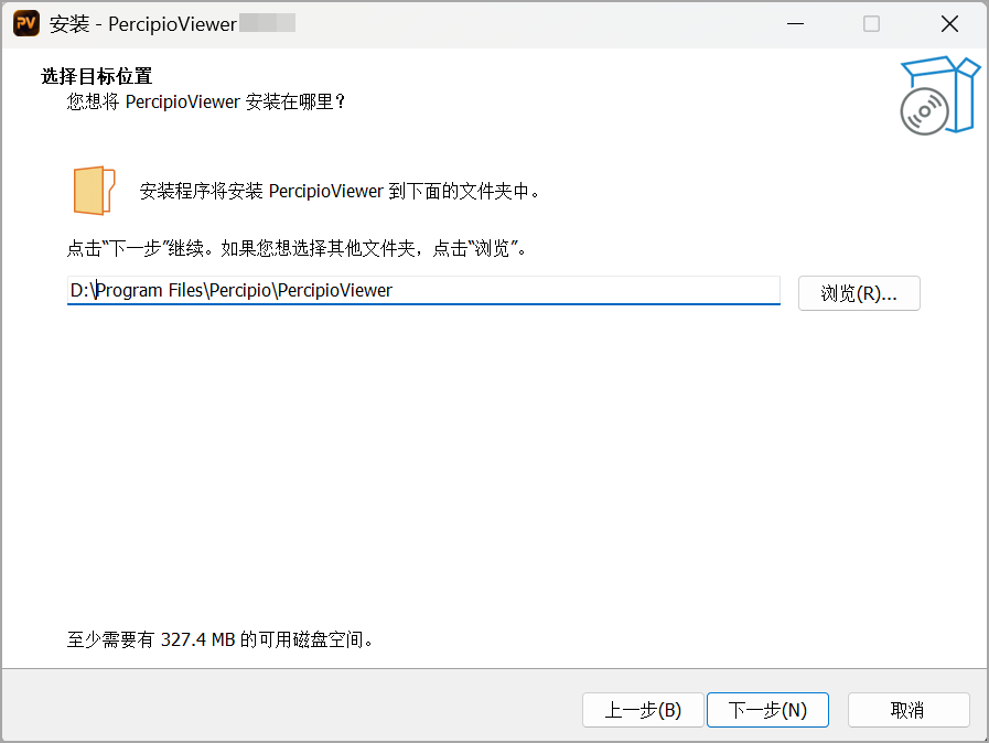
Choose the installation path and click Next.
Note
To avoid system permission restrictions, do not install the SDK on the C: drive (the system drive).
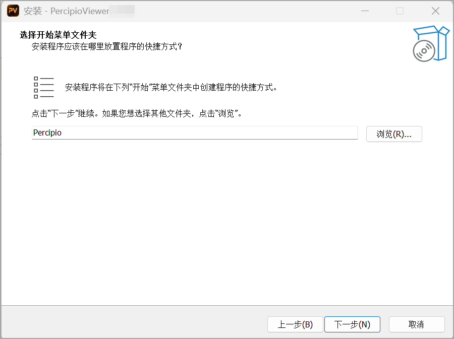
Choose a Start Menu folder for the application shortcuts, then click Next.
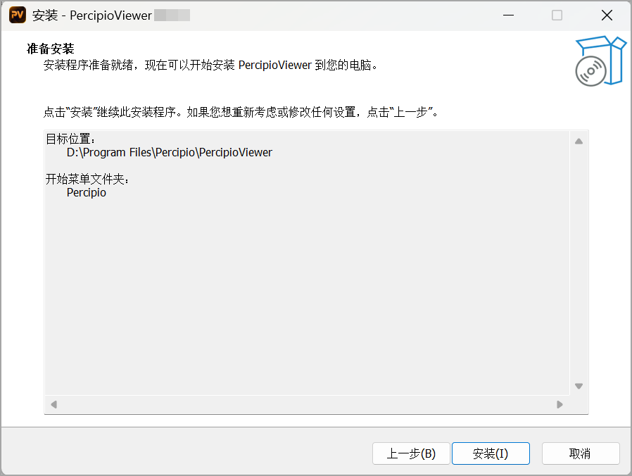
Click Install.
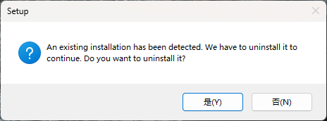
Note
If a previous version is detected, the following dialog will appear, prompting you to uninstall it. Select Yes to automatically uninstall the old version and proceed with installation, or No to cancel.
After installation is complete, click Finish.
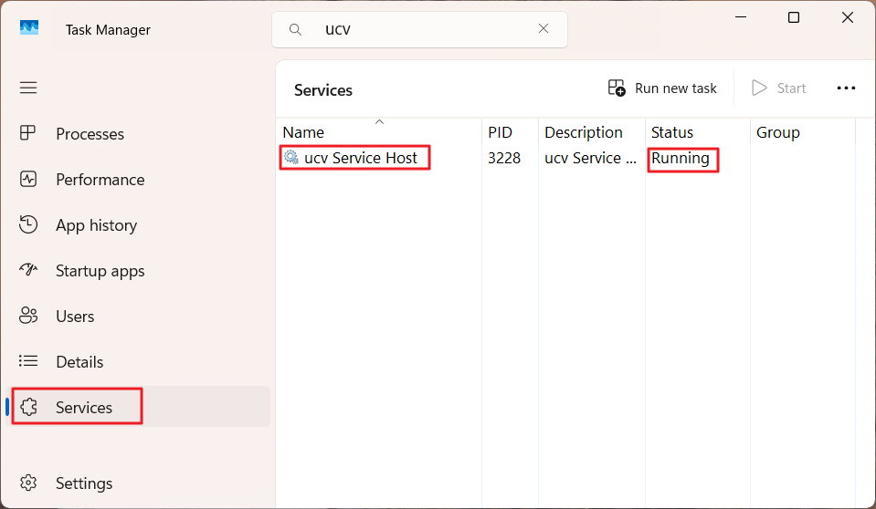
Important
Upon successful installation, the core background service “UcvCamWinServ” will start automatically. This service is essential for all SDK functionality. Ensure it is always running by checking the Services tab in the Windows Task Manager.
Launch Software
Double-click the shortcut icon ![]() to launch the software.
to launch the software.
Set IP Address
The camera can only be opened by the host host computer when both the camera and the host computer are set to the same network segment.
Configure Host Computer Network
It is recommended to configure the host computer’s network port to use a dynamic IP address.
Open the “Control Panel” on the host computer, select “Network and Internet” > “Network and Sharing Center” > “Change Adapter Settings”.
Right click on the current network connection, select “Properties” in the pop-up window.
Double click “Internet Protocol Version 4 (TCP/IPv4)” in the “Properties” window, and in the “Internet Protocol Version 4 (TCP/IPv4) Properties” dialog box that appears, select “Obtain an IP address automatically” and “Obtain DNS server address automatically”.
Click on “Confirm” to save the settings.

Windows Network Configuration: Use DHCP
Before configuring the computer network, please first confirm the camera’s network connection method. For specific connection details, refer to Network Connection Methods. Then follow the steps below to configure the computer network.
If the camera uses Network Connection Method 1 or Network Connection Method 2:
Open the computer’s network settings. Navigate sequentially to “Settings” > “Network” > “Change Settings” >
 to access the detailed configuration of the current connection.
In the IPv4 tab, select “Link-Local Only”. If there are any previously configured manual IP settings, remove all manually entered IP addresses, subnet masks, gateways, and DNS servers.

Local Network Configuration
Click “Apply” to save the settings.
The computer will successfully negotiate and obtain an IP address in the 169.254.xx.xx range.
If the camera uses Network Connection Method 3:
Open the computer’s network settings. Navigate sequentially to “Settings” > “Network” > “Change Settings” >
to access the detailed configuration of the current connection.In the IPv4 tab, select “Automatic (DHCP)”. If there are any previously configured manual IP settings, remove all manually entered IP addresses, subnet masks, gateways, and DNS servers.
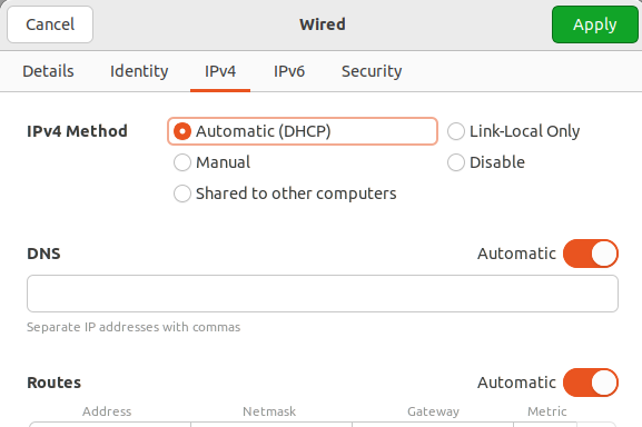
Local Network Configuration
Click “Apply” to save the settings.
After reconnecting to the network, the computer will obtain an IP address in the 192.168.xx.xx range from the DHCP server.
Camera Factory IP Configuration
The camera is configured with a dynamic IP address by default from the factory. This ensures that the camera can be opened normally when the computer’s network port is configured to use a dynamic IP address.
If you need to set the camera to use a static IP address, refer to Set Camera IP Address.
Set Camera IP Address
Prerequisites
Before setting a static IP address, ensure the host PC’s IP address is on the target subnet.
If the camera is currently connected to the software, disconnect it before setting the IP.
Procedure
On the Camera List page, click
 to refresh the camera list.
Click the serial number of the target camera to select it.
Click
Modify IPto open the Modify IP dialog.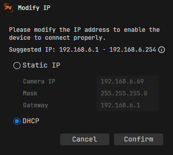
Modify IP
Set the camera IP.
Set as Static IP
Select “Static IP”.
Set “Camera IP”, “Mask” (Subnet Mask), and “Gateway” according to the interface prompts.
Set as Dynamic IP
Select “DHCP”.
Click
Confirm.The following Prompt dialog appears, indicating the IP setting was successful.
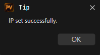
IP Set Successfully
Note
After the IP is set successfully, the camera list needs to be manually refreshed for the camera to appear in the list.
Capture Images
Launch Viewer.
To connect to a camera, double-click the camera list row or click the Connect icon
 in the camera list.
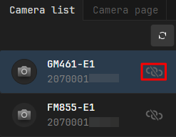
Connect Camera
Note
If there is no
icon next to the camera serial number, it means the camera cannot be connected currently. Click the serial number and check the status in the camera details to troubleshoot the connection issue.After connecting, the interface automatically switches to the Camera Page. Click
 at the top of the page to disconnect.
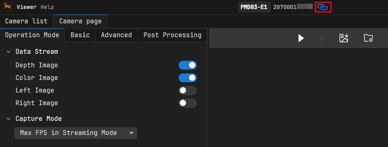
Disconnect from Camera Page
In the Data Stream field of the Operation Mode page, enable the corresponding data streams, such as “Depth Image” and “Color Image”.
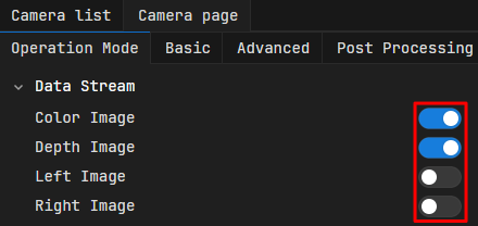
Enable Data Stream
Click
 in the image capture area to start capturing. Then click
  and
and  to turn the color and depth views on/off.
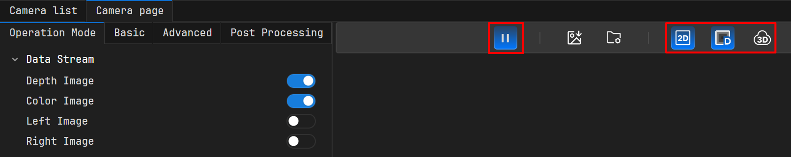
Start Capturing Images
For more operations of Viewer, please refer to Viewer User Guide.