TCP Standard Command Description
This article introduces the standard interface commands based on TCP/IP protocol.
Command Overview
RVS 2.0 TCP communication supports the following standard commands:
Command Description
Command Sending and Receiving
The robot or host computer, acting as the client, sends commands to the RVS 2.0 vision system, which acts as the server. After processing the command, the vision system returns the result to the robot or host computer.
Attention
The current version only supports this software running as a TCP server.
Command Data Transmission Format
Commands support two encoding formats: ASCII and HEX.
ASCII
ASCII format strings use English commas as data separators, and the ending terminator is \r. All examples in this article use ASCII format strings, and the ending terminator is omitted (\r).
For example, when the robot sends the 103 command to the vision system, if it includes the ending terminator, the command format is as follows:
103,1,2\r
HEX
HEX (hexadecimal) byte order is divided into big-endian and little-endian. When sending commands, the byte length is fixed at 64; if less than 64, it is padded with 0; if more than 64, the vision system will ignore the excess part.
Taking the ASCII format string “103,1,2” as an example, if sent in HEX big-endian form, the command format is as follows. Decimal 103 corresponds to hexadecimal 67, and its big-endian byte order representation is 00 00 00 67.
00 00 00 67 00 00 00 01 00 00 00 02 00 00 00 00 00 00 00 00 00 00 00 00 00 00 00 00 00 00 00 00 00 00 00 00 00 00 00 00 00 00 00 00 00 00 00 00 00 00 00 00 00 00 00 00 00 00 00 00 00 00 00 00
If sent in HEX little-endian form, the command format is as follows. The little-endian byte order representation of hexadecimal 67 is 67 00 00 00.
67 00 00 00 01 00 00 00 02 00 00 00 00 00 00 00 00 00 00 00 00 00 00 00 00 00 00 00 00 00 00 00 00 00 00 00 00 00 00 00 00 00 00 00 00 00 00 00 00 00 00 00 00 00 00 00 00 00 00 00 00 00 00 00
Command Data Units
Joint angles are measured in degrees (°).
A robot flange pose or robot tool pose consists of position and orientation. Position values (X, Y, Z) are measured in millimeters (mm), and orientation is expressed in Euler angles measured in degrees (°).
101 Command: Run RVS 2.0 Project
Function Description
This command starts the specified RVS 2.0 project. During execution, the vision system captures images, processes them, runs the configured algorithms, and then outputs a set of vision points.
Attention
Vision Point: The information unit used to describe a target object identified by the system. Each vision point contains the object’s pose, label, dimensions, and user-defined data.
Calling Sequence
Step parameters in the project need to be set before running the project. Therefore, 103 Command: Switch Parameter Recipe must be called before the 101 command.
Only after running the project can the vision system obtain vision points. Therefore, the 101 command must be called before 102 Command: Get Vision Results or 109 Command: Get User Label Data.
Sending Format
101,RVS 2.0 Project Number,Expected Vision Point Count,Robot Pose Type,Robot Pose
Parameters
Parameter |
Description |
|---|---|
RVS 2.0 Project Number |
View in the project list window. The number before the project name is the number. |
Expected Vision Point Count |
Expected number of vision points to obtain: |
Robot Pose Type |
Specifies the input form of robot pose: |
Robot Pose |
Pass corresponding data according to “Robot Pose Type”. See the table below for details. |
Robot Pose Type and Pose Data Description
Robot Pose Type |
Robot Pose Format |
Description |
Applicable Scenario |
|---|---|---|---|
0 |
0,0,0,0,0,0 (placeholder, actually invalid) |
Do not pass robot pose to the vision system. |
Used when camera is Eye To Hand and project does not require pre-photo capture. |
2 |
Robot’s current flange pose |
Pass the robot’s current flange pose for the vision system to calculate camera position. |
Applicable to most scenarios, especially Eye In Hand camera mounting. |
Return Format
101,Status Code
If the command executes successfully, the status code is 1102; otherwise, the corresponding error code is returned. See RVS 2.0 Error Codes for details.
Command Examples
Example 1: Eye In Hand Scenario, Passing Flange Pose
The robot sends the following command to the vision system (2 means the robot passes the current flange pose to the vision system), triggering project 1 to run:
101,1,1,2,350.25,150.72,480.36,-179.88,0.12,90.05
The vision system returns the following result to the robot (1102 means successfully triggered RVS 2.0 project):
101,1102
Example 2: Eye To Hand Scenario, Without Passing Flange Pose
The robot sends the following command to the vision system (robot pose type 0), triggering project 1 to run:
101,1,1,0,0,0,0,0,0,0
The vision system returns the following result to the robot (1102 means successfully triggered RVS 2.0 project):
101,1102
Example 3: Project Not Registered Error
The robot sends the following command to the vision system, requesting unregistered project 2:
101,2,1,0,0,0,0,0,0,0
The vision system returns the following result to the robot (1011 means RVS 2.0 project is not registered):
101,1011
102 Command: Get Vision Results
Function Description
This command is used to obtain the vision results (a series of vision points) output after the RVS 2.0 project runs. The object poses in the vision points (corresponding to the Any port data of the “Vision Output” step) have been converted by the vision system to the corresponding robot tool poses.
Calling Sequence
This command must be called after the 101 Command: Run RVS 2.0 Project has successfully run the project and after the 109 Command: Get User Label Data. After this command is called to retrieve data, the data of the “Vision Output” step is cleared.
Sending Format
102,RVS 2.0 Project Number,Vision Point Count This Time,Vision Point Index Numbers
RVS 2.0 Project Number
Must be consistent with the project number run in the 101 command.
Vision Point Count This Time (Optional)
Specifies the number of vision points to obtain this time, as a positive integer. If the actual number of vision points available for output is less than this value, all are returned; otherwise, only the specified number of vision points is returned.
Vision Point Index Numbers (Optional)
Specifies the index numbers of the vision points to obtain. Index starts from 0. For example, if there are currently 3 vision points and you want to obtain 2 this time, you can specify the desired combination by index number (for example, 0,1, 0,2, or 1,2).
Return Format
102,Status Code,Whether All Vision Points Have Been Obtained,Vision Point Count,Reserved Field,Vision Point 1(Tool Pose, Label, End Tool ID),Vision Point 2(Tool Pose, Label, End Tool ID),…
Parameter |
Description |
|---|---|
Status Code |
1100: Execution successful; others are error codes. See RVS 2.0 Error Codes for details. |
Whether All Vision Points Have Been Obtained |
0: Not all vision points have been obtained. |
Vision Point Count |
Number of vision points returned this time. |
Reserved Field |
Currently not used, fixed value is 0. |
Vision Point |
Each vision point consists of 8 pieces of data: |
Tool Pose Conversion Description
The vision system automatically converts the object pose of vision points (i.e., the Any port data of the “Vision Output” step) to the corresponding robot tool pose.
RVS 2.0 software internally uses quaternions to represent poses, but they are automatically converted to Euler angle form during command communication.
Command Examples
Example 1: Get a Single Vision Point
After the project runs, a total of 2 vision points are generated, obtained in 2 times, one vision point each time:
Run Project
The robot sends the 101 command to trigger project 2 to run (1 means expecting to obtain one vision point at a time):
101,2,1,2,352.10,148.33,479.85,-179.92,0.08,89.98
The vision system returns successful execution:
101,1102
Get the 1st Vision Result
The robot sends the 102 command to get the 1st vision point:
102,2
The vision system returns the 1st vision point:
102,1100,0,1,0,125.48,320.76,85.21,179.95,0.03,-90.12,0,0
Get the 2nd Vision Result
The robot sends the 102 command to get the 2nd vision point:
102,2
The vision system returns the 2nd vision point:
102,1100,1,1,0,130.25,315.42,82.15,178.92,1.25,-88.76,0,0
Example 2: Get Multiple Vision Points at Once
Taking obtaining 2 vision points as an example:
Run Project
The robot sends the 101 command to trigger project 2 to run (0 means expecting to obtain all vision points):
101,2,0,2,352.10,148.33,479.85,-179.92,0.08,89.98
The vision system returns successful execution:
101,1102
Get Vision Results
The robot sends the 102 command to get vision points:
102,2
The vision system returns 2 vision points:
102,1100,1,2,0,125.48,320.76,85.21,179.95,0.03,-90.12,0,0,130.25,315.42,82.15,178.92,1.25,-88.76,0,0
Example 3: Return When No Vision Results
Run Project
The robot sends the 101 command to trigger project 3 to run:
101,3,1,2,355.00,152.50,481.20,-179.95,0.15,90.10
The vision system returns successful execution:
101,1102
Get Vision Results
The robot sends the 102 command:
102,3
The vision system returns an error (currently no vision results):
102,1002
Example 4: Get Specified Vision Point Combinations by Index
After the project runs, a total of 3 vision points are generated. This time, only 2 are desired, and the 1st and 3rd vision points are specified through index numbers.
Run Project
The robot sends the 101 command to trigger project 4 to run (0 means expecting to obtain all vision points):
101,4,0,2,351.20,149.60,478.40,-179.90,0.10,90.00
The vision system returns successful execution:
101,1102
Get Vision Results by Index
The robot sends the 102 command. This time, 2 vision points are desired, and index 0,2 specifies the 1st and 3rd vision points:
102,4,2,0,2
The vision system returns 2 specified vision points:
102,1100,1,2,0,120.35,318.40,84.10,179.80,0.15,-89.95,1,0,133.72,309.18,81.64,178.55,1.02,-87.43,3,0
103 Command: Switch Parameter Recipe
Function Description
This command is used to switch the parameter recipe used by the RVS 2.0 project.
Calling Sequence
This command must be called before 101 Command: Run RVS 2.0 Project.
Sending Format
103,RVS 2.0 Project ID,Parameter Recipe Number
The parameters are described below:
RVS 2.0 Project ID
Check the project list window; the number before the project name is the project ID.
Parameter Recipe Number
Return Format
103,Status Code
If the command executes normally, the status code is 1107; otherwise, the corresponding error code is returned. See RVS 2.0 Error Codes for details.
Command Example
The robot sends the following command to the vision system, which switches the parameter recipe number of project 1 to 2.
103,1,2
If the vision system returns the following result, the command was executed normally. 1107 means the parameter recipe number of project 1 was successfully switched to 2.
103,1107
If the vision system returns the following result, the command was executed abnormally. 1012 means that no parameter recipe corresponds to the set recipe number.
103,1012
109 Command: Get User Label Data
Function Description
This command is used to obtain the user label data defined by the RVS 2.0 project (that is, the input to the User Label pin of the Vision Output step).
Calling Sequence
This command must be called after the 101 Command: Run RVS 2.0 Project has successfully run the project, and before the 102 Command: Get Vision Results.
Sending Format
109,RVS 2.0 Project Number
RVS 2.0 Project Number
Must be consistent with the project number run in the 101 command.
Return Format
109,Status Code,Reserved Field,User Label Count,Reserved Field,Label Data
Parameter |
Description |
|---|---|
Status Code |
1100: Execution successful; others are error codes. See RVS 2.0 Error Codes. |
User Label Count |
Number of user labels. |
User Label Data |
User label data. |
Command Example
Run Project
The robot sends the 101 command to the vision system to trigger project 1 to run:
101,1,0,2,350.25,150.72,480.36,-179.88,0.12,90.05
The vision system returns successful execution to the robot:
101,1102
Get User Label Data
The robot sends the 109 command to the vision system:
109,1
The vision system returns the result to the robot, indicating the command executed successfully (the input of the “User Label” pin of the Vision Output step is [1,2,3,4,5,6]):
109,1100,0,6,0,1,2,3,4,5,6
110 Command: Get Custom Data
Description
This command obtains custom port data from the “Vision Output” step and allows you to configure the input ports as needed.
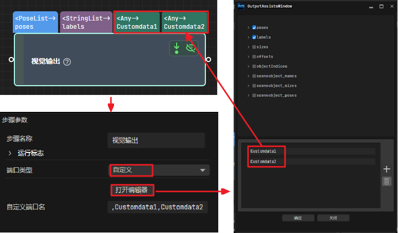
Attention
The data from the preset ports shown at the top of the figure, such as
poses,labels,sizes, andoffsets, is predefined data, not custom data.The Port Type parameter of the “Vision Output” step must be set to “Custom”, and the
posesport is required.
Calling Sequence
This command must be called after 101 Command: Run RVS 2.0 Project.
Sending Format
110,RVS 2.0 Project ID
RVS 2.0 Project ID
You can check the ID of an RVS 2.0 project in the Project List panel. The number before the project name is its ID.
Return Format
110,Status Code,Whether All Vision Points Have Been Obtained,Number of Custom Data,Pose,Label,Custom Data Item 1,…,Custom Data Item N
Status Code
Status code 1100 is returned on successful command execution. On failure, the corresponding error code is returned. See RVS 2.0 Error Codes for details.
Whether All Vision Points Have Been Obtained
This parameter indicates whether all vision points have been obtained. The value is 0 or 1.
0: Not all vision points have been obtained.
1: All vision points have been obtained.
Note
Each time the robot executes this command, it only obtains the pose and custom port output for only one vision point from the vision system. To obtain custom data for multiple vision points, execute this command multiple times.
This parameter value is 1 when all vision points are obtained. If the value is 0, repeat sending this command until the value becomes 1.
After the robot sends this command, the vision system returns a result in 10 seconds by default. If no result is returned in 10 seconds, the vision system returns an error code. You can modify the “Get Vision Data Timeout” value as needed in RVS 2.0 by going to the toolbar > Robot Communication Configuration > Next > Advanced Setting.
Number of elements in custom data
The total number of elements in the data output from all custom ports. For example, the outputs of the ports of the “Vision Output” step are shown in the following table. “customData1” and “customData2” are custom ports, with 3 and 2 columns in their respective output data. Therefore, the total number of elements in the custom output data is 5 (3 + 2).
Port Name |
poses |
labels |
customData1 |
customData2 |
|---|---|---|---|---|
Port Data |
[ |
[ |
[ |
[ |
[0, 0, 0, 1, 0, 0, 0], |
“0”, |
[0, 0, 1], |
[0, 0], |
|
[0, 0, 0, 1, 0, 0, 0], |
“1” |
[1, 0, 0] |
[1, 1] |
|
] |
] |
] |
] |
|
Number of rows (number of items in the list) |
2 |
2 |
2 |
2 |
Number of columns (number of elements in each item) |
7 |
1 |
3 |
2 |
Pose
This parameter indicates the robot tool pose for one vision point. The vision system converts the object pose of the vision point (that is, the output of the poses port of the “Vision Output” step) into the corresponding robot tool pose. The conversion process is as follows:
Convert the object pose from quaternion form to Euler angles.
Rotate the object pose 180° around the X-axis so that its Z-axis points downward.
Label
The label of a single vision point.
Note
The label must be a string in integer format.
If there is no label information, the label value defaults to 0.
Elements in custom data
Data output from all custom ports for a single vision point. The total number is specified by the number of elements in custom data parameter. The elements are arranged in alphabetical order (A–Z) of the custom port names.
For example, the data output from the ports of the “Vision Output” step is shown in the following table. The elements in the custom data of the first vision point are [0, 0, 1] and [0, 0], and those of the second vision point are [1, 0, 0] and [1, 1].
Port Name |
poses |
|||
|---|---|---|---|---|
Port Data |
[ |
[ |
[ |
[ |
[0, 0, 0, 1, 0, 0, 0], |
“0”, |
[0, 0, 1], |
[0, 0], |
|
[0, 0, 0, 1, 0, 0, 0], |
“1” |
[1, 0, 0] |
[1, 1] |
|
] |
] |
] |
] |
|
Number of rows (number of items in the list) |
2 |
2 |
2 |
2 |
7 |
1 |
3 |
2 |
|
First vision point |
[0, 0, 0, 1, 0, 0, 0] |
0 |
[0, 0, 1] |
[0, 0] |
Second vision point |
[0, 0, 0, 1, 0, 0, 0] |
1 |
[1, 0, 0] |
[1, 1] |
Command Example
Assume that the output of the ports of the “Vision Output” step in RVS 2.0 is as shown in the table below. The steps to obtain output data from the custom ports using 101 Command — Run Project and 110 Command — Get Custom Data are as follows:
The robot sends Command 101 to the vision system to obtain all vision points, that is, two in total.
101,1,0,0
The vision system returns the following result, indicating that Command 101 is successfully executed.
101,1102
The robot sends Command 110 to the vision system to obtain all data of the first vision point.
110,1
The vision system returns the following result. “11” and “21” are elements in the custom data.
110,1100,0,2,1150.1272,-297.2476,-55.0715,-0.1087,-1.6156,-176.1518,1,11,21
The robot sends Command 110 to the vision system to obtain all data of the second vision point.
110,1
The vision system returns the following result to the robot. “1” indicates that all vision points are obtained. “12” and “22” are elements in custom data.
110,1100,1,2,592.6891,-256.7424,-56.6007,0.0723,1.1348,-176.355,2,12,22
501 Command: Input Object Dimensions into an RVS 2.0 Project
Description
This command inputs object dimensions into an RVS 2.0 project. The input dimensions are the values of the Box Size Settings parameters of the “Read Object Dimensions” step, as shown below.
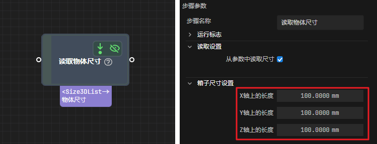
When using this command, the RVS 2.0 project can only contain one “Read Object Dimensions” step. Otherwise, the vision system returns an error.
Calling Sequence
This command must be called before 101 Command: Run RVS 2.0 Project.
Sending Format
501,RVS 2.0 Project Number,Object Dimension X,Object Dimension Y,Object Dimension Z
RVS 2.0 Project ID
You can check the ID of an RVS 2.0 project in the Project List panel. The number before the project name is its ID.
Object Dimension X/Y/Z
The length, width, and height of the object, in millimeters (mm). The values are read by the “Read Object Dimensions” step and written to the Length on X-axis, Length on Y-axis, and Length on Z-axis parameters respectively.
Return Format
501,Status Code
Status Code
Status code 1108 is returned on successful command execution. On failure, the corresponding error code is returned. See RVS 2.0 Error Codes for details.
Examples
The robot sends the following command to the vision system to set the object dimensions of project 1 to X=100 mm, Y=200 mm, Z=300 mm.
501,1,100,200,300
If the vision system returns the following result, the command was executed normally. 1108 means the object dimensions of project 1 have been set to X=100 mm, Y=200 mm, Z=300 mm.
501,1108
901 Command: Get System Status
Function Description
This command checks whether the RVS 2.0 project is ready.
Sending Format
901
Return Format
901,Status Code
Status Code
Status code 1101 is returned on successful command execution. On failure, the corresponding error code is returned. See RVS 2.0 Error Codes for details.
Examples
The robot sends the following command to the vision system:
901The vision system returns the result. “1101” indicates that the RVS 2.0 project is ready.
901,1101