Adapter Generator Guide
The Adapter Generator is a tool that quickly creates an Adapter program. With simple parameter configuration in the graphical interface, you can quickly create the corresponding Adapter program, and then perform secondary development on this basis to implement complex functions that the standard interface cannot meet.
Generate an Adapter Project
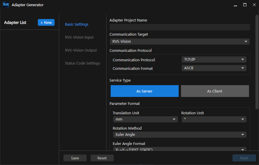
In the menu bar, select Robot and Communication > Adapter Generator to open the Adapter Generator window.
Attention
When configuring in the Adapter Generator window, keep the solution open so that the Adapter project can be saved correctly.
Configure Basic Settings
In the Basic Settings window, perform the following configuration:
Configuration Item
Description
Adapter Project Name
Specifies the Adapter project name. The project name is a string consisting of letters, digits, or underscores (it cannot start with a digit).
Communication Object
RVS-Vision. Only RVS-Vision input and output need to be configured.
Communication Protocol
TCP/IP
Communication Format
Specifies the data format for communication. Currently, only ASCII text is supported. If a HEX binary format is required, set the communication mode to
hexin the backend Adapter code (see Example: Binary Protocol).Service Type
Specifies whether the Adapter project acts as the server or client of TCP/IP communication.
The server listens for external connections; the client actively connects to external devices. The default is server.Translation Unit
mm (millimeter, default) and m (meter)
Rotation Unit
° (degree, default) and rad (radian)
Rotation Method
Usually select Euler Angle for the rotation method. When using Euler angles, they must be consistent with the rotation order of the robot controller. According to the robot type, select the corresponding format:
Z-Y’-X’’(ZYX_ROTATED): ABB / EPSON / ESTUN / KUKA / NACHIX-Y-Z(XYZ_STATIC): AUBO / DENSO / DOBOT / DELTA / EFORT / ELITE / FANUC / FLEXIV / FR / HANS / HYUNDAI / JAKA / MELFA / ROKAE / SIASUN / STEP / TM / YASKAWAZ-Y’-Z’’(ZYZ_ROTATED): COMAU / DOOSAN / KAWASAKI / QJARX-Y’-Z’’(XYZ_ROTATED): STAUBLI / TURINur_rot: UR
Decimal Precision
Specifies the number of decimal places of the data. The default is 4, and the selectable range is 1~20.
Field Separator
Specifies the separator character between data. The default is an English comma; common separators include the English comma, semicolon, and space.
Terminator
Specifies the end character of the command. The default is \r; common terminators are \n, \r, and \r\n.
Add Frame Prefix and Suffix
Specifies the leading and trailing characters of the whole command. After checking, you need to enter the leading and trailing characters; the default is an empty character. For example, if the command is “p,1\r”, using “<” as the leading character and “>” as the trailing character, the whole command becomes “<p,1>\r”. For detailed usage, see Example: ASCII Protocol with Frame Prefix and Suffix.
Note
An incorrect Euler-angle format will cause incorrect pose orientation. Before configuration, confirm whether the robot controller uses a static axis or a rotated axis, as well as the specific axis order.
After completing the above configuration, click Next to enter the RVS-Vision Input window.
Configure RVS-Vision Input
In the RVS-Vision Input window, set the command format that the robot or host computer sends to RVS-Vision. The specific configuration items include Take Photo Command, Set RVS-Vision Step Parameters, and Retrieve Robot Name from RVS-Vision.
Take Photo Command
Set the take-photo command of RVS-Vision.
Note
This command is mainly used to trigger the RVS-Vision project to run. In addition, this command can set the following functions as needed:
If the RVS-Vision project has parameter recipes, this command supports switching parameter recipes.
If the camera mounting method is Eye In Hand, or the RVS-Vision project has a “Path Planning” step, this command supports passing the robot capture pose into the RVS-Vision project.
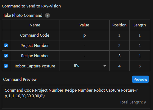
Configure the Take Photo Command according to the following instructions.
Table Description
Name: The name of each part in the whole command.
Parameter Value: The specific value corresponding to the name of each part.
Position: The starting position of each part in the whole command, numbered from 1. One separator marks the end of one position.
Length: The number of fields occupied by each part (a field refers to the data separated by the field separator).
Relationship between Position and Length: The starting position of the next parameter = the starting position of the previous parameter + the length of the previous parameter.
Name
Parameter Value
Position
Length
Command Code
The command code that triggers the RVS-Vision project to run. The default is p and can be modified.
Fixed at 1
Fixed at 1
Project Number
The RVS-Vision project number, a positive integer.
Fixed at 2
Fixed at 1
Recipe Number (Optional)
The number of the parameter recipe in the RVS-Vision project, a positive integer.
Configurable
Fixed at 1
Robot Capture Pose (Optional)
If the camera mounting method is Eye In Hand, this command passes the robot capture pose into the RVS-Vision project. This parameter can be set to JPs or “JPs+flange pose”.
Configurable
If Euler Angle is selected as the rotation method:
- If the pose form is JPs, fixed at 6
- If the pose form is “JPs+flange pose”, fixed at 12
- If the pose form is JPs, fixed at 6
- If the pose form is “JPs+flange pose”, fixed at 13
Note
Each field has a position and a length. The position starts from 1, and the command code is usually located at field 1. The ranges occupied by the fields must not overlap. Empty positions can be reserved according to the protocol requirements.
ASCII example:
p,1,2,0.0,10.0,20.0,30.0,40.0,50.0\r
This example can be interpreted as follows:
p: Command code1: Project number2: Recipe numberThe following 6 numbers: robot joint angles.
If “JPs+flange pose” is selected, the pose field contains at least 12 numbers: the first 6 are joint angles, and the following data are the flange position and rotation. The specific length is determined by the selected rotation method.
Click the highlighted cells in the Parameter Value, Position, and Length columns to modify their values as needed.
Attention
When modifying, pay attention to the following:
The command code must be unique for different commands.
The field positions occupied by different parameters must not overlap. For example, the position of the robot capture pose is 3 and its length is 12. If the position of the recipe number is 4 and its length is 1, then the second field position of the robot capture pose overlaps with the position of the recipe number. If the position of the recipe number is greater than or equal to 15, the positions of the robot capture pose and the recipe number will not overlap.
If there are gaps between the positions of the parameters, 0 is used to fill them by default. During preview, the gap positions are displayed as Reserved Positions with a value of 0. For example, if the position of the recipe number is 3 and its length is 1, and the position of the robot capture pose is 6 and its length is 12, positions 4 and 5 are empty. If the position of the robot capture pose is changed to 4, the empty positions can be eliminated. It is recommended to eliminate unnecessary empty positions by modifying the positions.
After completing the above configuration, click Preview to generate the corresponding command example based on the configuration items.
Tip
In the Command Preview window, hover the mouse cursor over a field name, and the field name and its corresponding data will be highlighted.
Set RVS-Vision Step Parameters (Optional)
If the step parameters cannot be preset with parameter recipes, or the step parameters need to be set based on external information, check Set RVS-Vision Step Parameters to configure the “Set RVS-Vision Step Parameters” command.
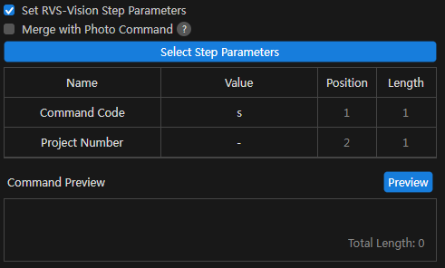
Before configuration, confirm:
The workflow and step are selected correctly.
The property path matches the target parameter.
The field positions and field lengths comply with the external protocol.
The data type of the external value can be converted to the target property type.
The parameter modification happens before the workflow is executed.
Select whether to check Merge with Take Photo Command.
Note
Merge with Take Photo Command means merging the command for setting RVS-Vision step parameters into the take-photo command, that is, appending the step-parameter fields to the take-photo command.
The Set RVS-Vision Step Parameters command can be merged with the take-photo command into one command, or it can be a separate command (in this case, it must be called before the take-photo command). The applicable scenarios of the two methods are as follows:
An independent command is suitable for the control flow of first setting multiple parameters and then triggering the photo.
A merged command is suitable for completing parameter update and photo triggering in one message.
Checked: The configuration items in the following table reuse the settings of the take-photo command, so you can directly proceed to step 2.
Not checked: Configure the “Set RVS-Vision Step Parameters” command separately according to the following table.
Name
Parameter Value
Position Length Command Code
The command code for setting RVS-Vision step parameters. The default is s and can be modified.
Fixed at 1 Fixed at 1 Project Number The RVS-Vision project number, a positive integer.
Fixed at 2 Fixed at 1 Recipe Number (Optional)
The number of the parameter recipe in the RVS-Vision project, a positive integer.
Configurable Fixed at 1 Select the step parameters.
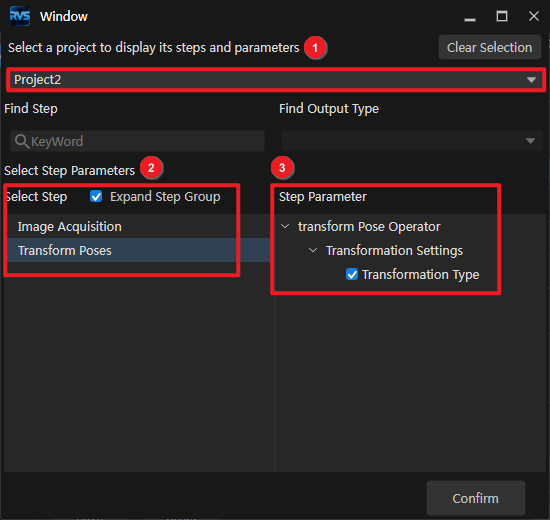
Click Select Step Parameters. In the pop-up window, select the step parameters according to the following operations:
a. Select a project in the solution to display the steps to be set and the corresponding parameter names.
b. Under the Select Step option, select the step to be set.
c. Under the Step Parameters option, expand and check the parameter names of the step.
d. Click OK.
Note
If Set RVS-Vision Step Parameters is checked, step parameters must be selected; otherwise, an error message appears.
Multiple steps and parameters can be selected.
If the data type of the step parameter value is Boolean, 1 represents true and 0 represents false.
Click the highlighted cells in the Parameter Value, Position, and Length columns to modify their values as needed.
Attention
When modifying, pay attention to the following:
The field positions occupied by different parameters must not overlap.
If there are gaps between the positions of the parameters, 0 is used to fill them by default. It is recommended to eliminate unnecessary empty positions by modifying the positions.
After completing the above configuration, click Preview to generate the corresponding command example based on the configuration items.
See also
For the complete configuration of independent and merged commands, see Example: Setting Vision-Step Parameters Separately.
Retrieve Robot Name from RVS-Vision (Optional)
Click Retrieve, and the name of the robot selected in Robot Communication Configuration will be displayed in the input box.
The retrieved robot name is used to register the robot service. In the Robot Communication Configuration interface, different robot options result in different robot names retrieved here.
Robot Option
Robot Name
Brand robot
Specific robot name and model
Other robot
RobotType1
No robot
No robot found
After completing the above configuration, click Next to enter the RVS-Vision Output window.
Configure RVS-Vision Output
In the RVS-Vision Output window, set the data format that RVS-Vision returns to the robot or host computer. The specific configuration items include Pose Data, Object Label, and Other Output.
Determine the corresponding configuration items according to the “Vision Output” step of the RVS-Vision project.
Port Type of the “Output” Step
Port Name
Configuration Item
Applicable Scenario
Predefined (Vision Result)
poses
Pose Data (Vision Point Data)
Obtain the pose of the target object
Predefined (Vision Result)
poses, labels
Pose Data (Vision Point Data), Object Label
Obtain the pose and label of the target object
Custom
Custom port name
Other Output
Obtain custom data, for example, OCR text, VIN code, measurement results, etc.
Select whether to check Pose Data (default: checked).
If Vision Point Data is selected for configuration, refer to the following table for configuration.
Attention
If the rotation method in Basic Settings is Quaternion, each output pose occupies 7 fields.
Configuration Item
Description
Quantity
Configurable items: 1, fixed value (manually entered), all.
- 1: RVS-Vision outputs N vision points, but the Adapter returns only the first vision point.
- Fixed value M: RVS-Vision outputs N vision points, but the Adapter returns only the first M vision points.
- All: RVS-Vision outputs N vision points, and the Adapter returns N vision points.
Send the Number of Poses
The data returned by RVS-Vision will carry the number of poses returned this time, and the number of poses will be located before the pose data.
Convert Object Pose to Robot Pose
Automatically rotates the pose of the RVS-Vision recognition result by 180° around the X axis (making its Z axis point downward), so that the robot can directly move to this pose for grasping.
Select whether to check Object Label. The object label is the data of the labels port of the “Vision Output” step.
Select whether to configure Other Output. Click + to configure multiple ports.
Attention
The list size of the custom port data should be consistent with that of the labels or poses.
Configuration Item
Description
Port Name
The custom port name of the “Vision Output” step.
Data Type
Configurable items: Stringlist, Numberlist, Size3DList.
After completing the above configuration, click Preview to generate the corresponding command example based on the configuration items. After confirming it is correct, click Next to enter the next configuration interface.
Note
A typical ASCII success response is as follows:
1,2,100.0000,20.0000,500.0000,180.0000,0.0000,90.0000,...\r
The first field is the external status code, the second field is the number of poses, and the following fields are the pose data expanded according to the configured format. The actual field order is subject to the command preview in the generator.
Configure Status Codes
In the Status Codes window, set the corresponding status codes for various processing results of the commands.
The Adapter Generator supports the following status codes by default:
Status
Default External Status Code
Success
1
Invalid command
2
Project not loaded
3
No point cloud
4
No result
5
Path planning failed
6
Invalid step parameter
7
Timeout
8
Other error
9
Tip
You can add or remove status codes as needed.
Remove status codes: Set different status codes to the same value. For example, set “Invalid command” and “Project not loaded” both to 2.
Add status codes: Modify the status code mapping in the Adapter code (
status_code_map.pyor a custom Assembler). For specific methods, see Adapter Programming Guide: Internal Error Codes.
After completing the above configuration, click Save and Generate. In the confirmation window that pops up, click Yes to save all configurations.
Attention
Before saving, check the input and output previews item by item:
Whether the field order, positions, and lengths are correct;
Whether the command code is consistent with the external program;
Whether the ASCII separator, terminator, and prefix/suffix are correct;
Whether the length unit, rotation unit, and Euler-angle format are correct;
Whether the status codes are consistent with the external program.
After saving the configuration, the system writes the Adapter configuration and generates Python code. The generated directory mainly contains:
<Adapter Configuration Directory>/
├── configurational_adapter.json
├── generated/
│   ├── __init__.py
│   ├── header_parser.py
│   ├── parser_trigger.py
│   ├── parser_setprop.py       # Generated when the independent step-parameter command is configured
│   ├── assembler.py
│   ├── status_code_map.py
│   └── register.py
└── .vscode/
    └── launch.json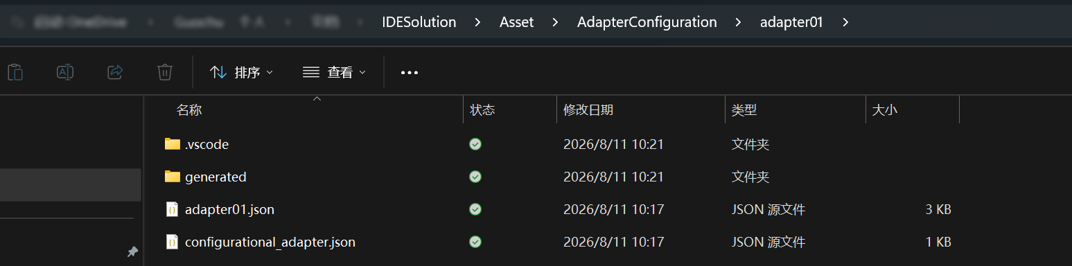
Note
The files in
generated/will be overwritten when the configuration is saved again and should not be modified directly. To change conventional fields, modify the generator configuration and regenerate. To truly extend the generation logic, modify the generator templates or create an independent custom protocol package.See also
For the complete configuration and joint debugging process, see Example: Robot Triggers Vision and Obtains Pick Poses.
Deploy the Adapter Project
After completing the Adapter Generator configuration, deploy the Adapter project according to the following steps.
In the RVS 2.0 menu bar, click Robot and Communication > Robot Communication Configuration.
In the Robot Communication Configuration window, perform the following configuration.
a. Select the robot and click Next.
b. Under Interface Service Type, select Adapter.
c. Under Adapter Project Folder, click
 . In the file browser that pops up, select the Adapter project folder.
d. Set the Host IP Address. The default value is 0.0.0.0, which means listening on all IP addresses.
e. Click Apply.
In the RVS 2.0 main interface, confirm that the interface service on the toolbar is enabled.

At this point, the Adapter project is deployed successfully.
Joint Debugging of the Adapter Project
Configure the Network
If the Adapter acts as a TCP server:
Set the listening address to the local NIC address, or use
0.0.0.0to listen on all NICs;The port must not be occupied by other programs;
The external device should actively connect to the IP and port of the industrial PC running the Adapter.
If the Adapter acts as a TCP client:
Set the host address to the IP of the external device;
Confirm that the external device has started its TCP service;
After the connection is disconnected, the Adapter will retry reconnecting according to the configured reconnection interval.
Send Test Commands
It is recommended to use a network debugging tool to verify the protocol before connecting to the robot or PLC.
The test sequence is as follows:
Start and load the vision project to be run;
Start the Adapter;
Establish the TCP connection;
Send a valid command with the fewest fields;
Confirm that the Adapter log recognizes the correct command code;
Confirm that the vision workflow is executed;
Check the status code and data fields against the response preview;
Then add optional fields such as recipes, robot poses, and step parameters.
TCP is a byte-stream protocol. The current communication layer hands the data obtained by each
read()to the protocol layer without automatically buffering and splitting frames by the terminator. Therefore, during joint debugging, the external device should send one complete request at a time and wait for the response before sending the next one. For production protocols that may suffer from packet splitting, packet sticking, single frames exceeding the receive buffer, or high-frequency continuous sending, the communication layer should be extended with frame buffering and splitting based on fixed length, length fields, or terminators before putting into field use.
Example: Robot Triggers Vision and Obtains Pick Poses
This section uses a complete example to explain how to go from requirement definition and generator configuration all the way to message joint debugging. The example objectives are as follows:
The Adapter acts as a TCP server listening on port
50000;The robot sends ASCII commands;
One command contains the project number, recipe number, and 6 joint angles;
The Adapter switches the recipe, writes the robot pose, and executes the vision workflow;
The Adapter returns the status code, number of poses, pick poses, and object labels;
Fields are separated by commas, and the message ends with
\r;The length unit is millimeter, the rotation unit is degree, and the output pose is
ZYX_STATICEuler angles;Floating-point numbers retain 3 decimal places.
Define the Communication Protocol First
Before opening the generator, confirm the protocol fields with the robot program developer. Do not decide the fields temporarily while configuring; otherwise, the robot side and the Adapter side can easily become inconsistent in positions.
Take-photo request field table:
Type |
Example |
Description |
|||
|---|---|---|---|---|---|
1 |
|
String |
1 |
|
Take-photo trigger command code. |
2 |
|
Unsigned integer |
1 |
|
Vision project number. |
3 |
|
Unsigned integer |
1 |
|
The recipe number to switch to. |
4 ~ 9 |
|
Float array |
6 |
|
Robot six-axis joint angles. |
Complete request:
P,1,2,0,10,20,30,40,50\r
Field-by-field breakdown:
P  , 1 , 2 , 0 , 10 , 20 , 30 , 40 , 50 \r
│    │   │   └──────────────┬──────────────┘  │
│    │   │                  │                  └─ Message terminator
│    │   │                  └─ J1~J6
│    │   └─ Recipe number
│    └─ Project number
└─ Command code
Success response field table:
Order |
Field |
Type |
Example |
Description |
|---|---|---|---|---|
1 |
|
Integer |
|
Success status code. |
2 |
|
|
2 poses returned this time. |
|
3 ~ 8 |
|
6 floats |
|
X, Y, Z, Rx, Ry, Rz of the first pose. |
9 |
|
String |
|
Label of the first object. |
10 ~ 15 |
|
6 floats |
|
The second pose. |
16 |
|
String |
|
Label of the second object. |
Complete success response:
1,2,100.000,20.000,500.000,180.000,0.000,90.000,box_A,120.000,25.000,498.000,180.000,0.000,88.000,box_B\r
No vision result response:
5\r
Invalid command response:
2\r
Whether the failure response contains only the status code should be fixed during the protocol design phase. The robot side should not continue reading the pose count and pose fields in the failed state.
Create and Prepare the Vision Project
Create or open a vision project for grasping and positioning in RVS 2.0.
Confirm that there is an executable workflow in the project.
Confirm that the workflow output contains pick poses.
If labels need to be returned, confirm that the vision results contain labels corresponding to each pose.
Create at least two recipes to verify recipe switching.
Manually run the workflow to confirm that stable results can be obtained without the Adapter.
Configure Basic Settings
In the Adapter Generator, fill in:
Configuration Item |
Example Value |
|---|---|
Project Name |
|
Protocol |
|
Data Format |
|
Service Type |
|
Port |
|
Length Unit |
|
Rotation Unit |
|
Rotation Method |
|
Euler Angle Format |
|
Decimal Precision |
|
Field Separator |
|
Terminator |
|
Frame Prefix/Suffix |
Disabled |
Configure the Input Command
Set the take-photo trigger command code to
P.Enable the project number and set its position to 2.
Enable the recipe number and set its position to 3.
Enable the robot capture pose.
Select
JPsas the pose type.Set the pose position to 4 and the length to 6.
Confirm in the command preview that the last joint angle is at position 9.
The logical fields after configuration should be:
1:P | 2:project_id | 3:recipe_id | 4~9:joint_angles
Configure the Output
Enable “Return Pose Data”.
Select “Vision Point Data” as the data type.
Select “All” as the return quantity.
Enable “Return the Number of Poses”.
Decide whether to enable “Convert to Robot Pose” according to the field coordinate definition.
Enable “Return Object Label”.
Do not add other output ports.
Configure Status Codes and Save
This example uses the default status codes 1~9. After saving, check:
robot_pick_demo/
├── configurational_adapter.json
└── generated/
    ├── header_parser.py
    ├── parser_trigger.py
    ├── assembler.py
    ├── status_code_map.py
    └── register.py
The core execution order generated by the generator for this example is equivalent to:
workflow = await get_workflow_id.submit(
    exec_ctx,
    params={"project_id": project_id},
)

await switch_recipe.submit(
    exec_ctx,
    params={"project_id": project_id, "recipe_id": recipe_id},
)

await set_robot_pose.submit(
    exec_ctx,
    params={"project_id": project_id, "joint_angles": joint_angles},
)

await execute_workflow.submit(
    exec_ctx,
    params={"flow_id": workflow.data["workflow_id"]},
)

result = await get_vision_result.submit(
    exec_ctx,
    params={"flow_id": workflow.data["workflow_id"], "timeout": 30000},
)
This code is for understanding the execution order only; you do not need to copy it into the generated files.
Simulate the Robot with Python
You can use the following script to connect to the Adapter and send a request:
import socket

HOST = "127.0.0.1"
PORT = 50000
REQUEST = b"P,1,2,0,10,20,30,40,50\r"

with socket.create_connection((HOST, PORT), timeout=5) as client:
    client.sendall(REQUEST)
    client.settimeout(35)

    response = bytearray()
    while not response.endswith(b"\r"):
        chunk = client.recv(4096)
        if not chunk:
            raise ConnectionError("Adapter closed the connection")
        response.extend(chunk)

print("raw:", bytes(response))
print("text:", response.decode("utf-8").rstrip("\r"))
If the Adapter runs on another industrial PC, change HOST to the actual NIC IP of that PC.
Parse the Response
The robot side can process the response with the following logic:
def parse_response(message: str):
    fields = message.rstrip("\r").split(",")
    status = int(fields[0])
    if status != 1:
        return {"status": status, "poses": []}

    count = int(fields[1])
    cursor = 2
    poses = []

    for _ in range(count):
        pose = [float(value) for value in fields[cursor:cursor + 6]]
        cursor += 6
        label = fields[cursor]
        cursor += 1
        poses.append({"pose": pose, "label": label})

    if cursor != len(fields):
        raise ValueError("Response contains unexpected trailing fields")

    return {"status": status, "poses": poses}
During joint debugging, perform at least the following tests:
No. |
Request or Field Condition |
Expected Result |
|---|---|---|
1 |
Valid project, recipe, and joint angles |
Returns status code 1 and poses. |
2 |
Unknown command code |
Returns the invalid command status code 2. |
3 |
Non-existent project number |
Returns the project-not-loaded status code 3. |
4 |
No target object in the scene |
Returns the no-result status code 5. |
5 |
One joint angle missing |
Returns an error status, and the Adapter should not execute the workflow. |
6 |
Recipe does not exist |
Returns a failure status, and the workflow should not continue. |
7 |
Vision execution exceeds the timeout |
Returns the timeout status code 8. |
8 |
TCP disconnected during processing |
The Adapter remains available and allows reconnection. |
Example: Setting Vision-Step Parameters Separately
This example uses a separate command to modify vision step parameters before taking the photo. Assume that “Match Mode” and “Minimum Confidence” need to be modified.
Define the Command
Step-parameter command:
S,1,0,0.850\r
Position |
Field |
Example |
Description |
|---|---|---|---|
1 |
Command code |
|
Set the parameter. |
2 |
Project number |
|
Target vision project. |
3 |
Match mode |
|
In the example, |
4 |
Minimum confidence |
|
Floating-point parameter. |
Take-photo command:
P,1\r
Recommended control sequence:
Robot                    Adapter                     Vision System
  │ S,1,0,0.850\r           │                          │
  ├────────────────────────►│ Update step property     │
  │                          ├─────────────────────────►│
  │ 1\r                      │                          │
  │◄────────────────────────┤                          │
  │ P,1\r                    │                          │
  ├────────────────────────►│ Execute workflow and get results │
  │                          ├─────────────────────────►│
  │ 1,1,...\r                │                          │
  │◄────────────────────────┤                          │
The robot must wait until the parameter-setting command returns success before sending the take-photo command. Otherwise, the photo may still use the old parameters.
Select Properties in the Generator
Enable “Set Vision Step Parameters”.
Do not enable “Merge with Take Photo Command”.
Set the step-parameter command code to
S.Select “Match Mode” from the vision project.
Then select “Minimum Confidence”.
Set positions 3 and 4 respectively, both with a length of 1.
After saving, confirm that
parser_setprop.pyis generated.
The generated code saves the workflow ID, step ID, property path, and property type of each property. The protocol input value is converted into the JSON data required by the vision system according to the property type.
How common properties are expanded in the message:
Property Type |
ASCII Input Example |
Number of Fields |
|---|---|---|
|
|
1 |
|
|
1 |
|
|
1 |
Enum |
|
1 |
|
|
2 |
|
|
3 |
Quaternion pose |
|
7 |
The property type and length must be consistent with the generator preview. If the configured length is shorter than required by the target property, parsing or property update may fail; if it is too long, the extra fields will misalign the following fields.
Merge Step Parameters and Take-Photo Command
If “Merge with Take Photo Command” is enabled, you can use:
P,1,0,0.850\r
The Adapter executes the following sequence within the same request:
Get the workflow ID;
Update the match mode;
Update the minimum confidence;
Execute the workflow;
Get and return the vision results.
If any property update fails, the workflow should not be executed.
Example: ASCII Protocol with Frame Prefix and Suffix
Some robot protocols require a frame to start and end with fixed strings. For example:
<STX>P,1<ETX>
Configure in the generator:
Configuration Item |
Value |
|---|---|
Enable Prefix/Suffix |
Yes |
Prefix |
|
Suffix |
|
Separator |
|
The parsing rules are as follows:
The input must start with the prefix;
The input must end with the suffix;
The prefix and suffix are not passed to the Payload Parser as command fields;
The output status code and business data are also wrapped with the same prefix and suffix;
No separator is automatically inserted between the prefix/suffix and the business fields.
Success response example:
<STX>1,1,100.000,20.000,500.000,180.000,0.000,90.000<ETX>
The following inputs should all be judged as invalid:
P,1<ETX>          # Missing prefix
<STX>P,1          # Missing suffix
<STX>,P,1<ETX>    # Extra separator after the prefix
Example: Binary Protocol
The binary mode is suitable for device protocols with fixed field widths. The hex mode of the current TCP server requires the sender to transmit ASCII hexadecimal text; after receiving the text, the communication layer removes spaces and uses bytes.fromhex() to convert it into raw bytes, and then passes them to the protocol parser. In the current generator, the command code is recognized from the first 4 bytes after conversion, and numeric fields are read according to the configured byte order.
Assume the protocol uses little-endian order, with the request structure:
Byte Offset |
Length |
Field |
Type |
Example |
|---|---|---|---|---|
0 |
4 |
Command code |
4 bytes |
|
4 |
4 |
Project number |
|
|
8 |
24 |
Six-axis joint angles |
6 × |
Encoded in IEEE 754 little-endian |
Construct the request with Python:
import socket
import struct

command = b"\x01\x00\x00\x00"
project_id = struct.pack("<I", 6)
joints = struct.pack("<6f", 0.0, 10.0, 20.0, 30.0, 40.0, 50.0)
request = command + project_id + joints
# The hex mode of the TCPServer receives ASCII hex text, not the raw bytes of request directly.
wire_data = request.hex().encode("ascii")

with socket.create_connection(("127.0.0.1", 50000), timeout=5) as client:
    client.sendall(wire_data)
    response = client.recv(4096)
    print(response.hex(" "))
For example, the raw bytes of the command code and project number are:
01 00 00 00 06 00 00 00
The first 16 ASCII characters actually sent over the wire are:
0100000006000000
The binary response of the Adapter is directly assembled into bytes by the Assembler. The external device should parse it according to the response structure and byte order agreed by both parties, and should not treat the response as an ASCII hexadecimal string unless a custom Assembler explicitly performs such encoding.
The binary joint debugging must clarify:
Whether the 4 bytes of the command code are a numeric encoding or a raw byte sequence;
Whether little-endian or big-endian is used;
Whether the integer is signed;
Whether the floating-point number uses 32-bit or 64-bit;
How the total message length is determined;
Whether a length field, checksum, or escape is needed;
How to buffer when one TCP receive does not contain a complete frame.
If the protocol includes CRC, dynamic length, escape, or multiple different frame headers, it is recommended to use a custom Header Parser instead of forcing the fixed-field generator.