3D Coarse Matching
Function Description
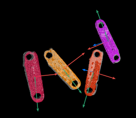
This Step coarsely matches the point cloud model with the original point clouds and outputs the coarsely calculated candidate poses of the target objects.
Use Cases
This Step is typically used to detect the target object in the scene point cloud and obtain its approximate candidate poses. It is usually used together with the “3D Fine Matching” Step.
Input
Point Cloud with Normals (Required): Scene point cloud data with normal vector information to be matched.
Surface Template Point Cloud (Optional): Surface template point cloud for coarse matching.
Edge Template Point Cloud (Optional): Edge template point cloud for coarse matching.
Geometric Center Pose (Optional): The geometric center point pose of the workpiece.
Output
Coarsely Calculated Poses: Coarse candidate poses of the target object, which need to be filtered and optimized by “3D Fine Matching”.
Matching Scores: The unnormalized matching score for each pose.
Parameters
Parameter Tuning Level
Parameter Tuning Level
Value list: Basic, Advanced
Basic: Shows core parameters and is suitable for most common scenarios.
Advanced: Shows all parameters and is suitable for complex scenarios that require fine tuning.
Basic Parameters
Model Selection
Select a model from the Workpiece Library.
Tuning tip: After creating a point cloud model in the Workpiece Library, click the dropdown button on the right side of this parameter to quickly select or switch point cloud model files.
Matching Mode
Used to select the matching mode for 3D coarse matching. If the point cloud model represents the edge of the workpiece, select “Edge Matching”. If the point cloud model represents the surface of the workpiece, select “Surface Matching”.
Expected Point Count of Sampled Model
Used to set the expected number of points in the downsampled point cloud. The smaller this value, the fewer points remain in the downsampled point cloud, and the lower the matching accuracy.
Expected Number of Detected Poses per Input Point Cloud: Sets the expected number of matching results to obtain from each input point cloud.
Advanced Parameters
Model Settings
Model Selection
Used to select the point cloud model file from the Workpiece Library.
Tuning tip: After creating a point cloud model using the Workpiece Library, click the dropdown button on the right side of this parameter to quickly select or switch point cloud model files.
Matching Mode
Select based on the point cloud model. If the point cloud model represents the edge of the workpiece, select “Edge Matching”; if the point cloud model represents the surface of the workpiece, select “Surface Matching”.
Preprocessing Settings
Expected Point Count of Sampled Model
Sets the expected number of points in the downsampled point cloud. The smaller this value, the fewer points remain in the downsampled point cloud, and the lower the matching accuracy.
Feature Search Radius Quantization
Sets the range for computing features in the scene. Feature Search Radius = Feature Search Radius Quantization × Model Diameter. The smaller this value, the lower the matching accuracy, but the faster the speed.
Tuning tip: For workpieces with large diameters, reduce this value to improve search speed. For workpieces with sparse features, increase this value to improve matching accuracy.
Voting Settings
Distance Quantification
used to quantify the distance between points in the object point cloud. Distance Interval = Distance Quantification × Sampling Step. The greater this value is, the less accurate the matching result tends to be.
Tuning tip: For workpieces with long cylindrical features, if axial precision is insufficient, adjust this parameter to 0.5. If workpiece features are sparse and the target cannot be found, adjust this parameter to 2.0 to improve stability.
Angle Interval
Used to discretize the angle between the feature normal vectors of points.
The smaller this value, the higher the matching accuracy, but higher quality point clouds are required.
Voting Ratio Lower Threshold
Poses with scores higher than “Highest Score in Voting × Voting Ratio Lower Threshold” will be used for pose verification. The lower this value, the more poses are used for pose verification, the greater the chance of finding accurate matching results, but the longer the runtime.
Reference Point Sampling Step Length
Sets the sampling interval for sampling points on the point cloud template. The larger the step length, the fewer the sampling points, the faster the execution speed, but the lower the matching accuracy; the smaller the step length, the more the sampling points, the higher the matching accuracy, but the slower the execution speed.
Tuning tip: For workpieces with sparse features or elongated shapes, reduce this value to increase matching stability.
Pose Verification Settings
Maximum Overlap Ratio
Filters out other pose workpieces whose overlap ratio is greater than this value.
Reference Coordinate System
Determines whether the filtering limit is based on the camera coordinate system or the robot coordinate system, that is, whether the scene coordinate system is the camera coordinate system or the robot coordinate system.
Tuning tip: If the camera shooting pose is not fixed, only the robot coordinate system can be selected.
Position Filter
Selects a target point on the model object, and a reference point and reference direction in the scene. Matching results are retained when the distance from the target point to the reference point along the reference direction falls within the allowed range; otherwise, they are filtered out.
Click the “Settings” button to open the Position Filter Tool interface, click “+”, and configure the following parameters:
Model Coordinate System Point: A target point on the coordinate system of the model object (geometric center point).
Scene Coordinate System Point: A reference point on the scene coordinate system (camera or robot coordinate system).
Scene Coordinate System Direction: A reference direction on the scene coordinate system (camera or robot coordinate system).
Minimum Distance: The minimum distance from the target point along the reference direction to the reference point.
Maximum Distance: The maximum distance from the target point along the reference direction to the reference point.
Tuning tip: Applicable when objects in the scene have position constraints, such as being placed on a fixed planar workbench.
Direction Filter
Selects a target direction on the model object and a reference direction in the scene. Matching results are retained when the angle between the target direction and the reference direction falls within the specified range; otherwise, they are filtered out.
Click the “Settings” button to open the Direction Filter Tool interface, click “+”, and configure the following parameters:
Model Coordinate System Direction: A target direction on the coordinate system of the model object (geometric center point).
Scene Coordinate System Direction: A reference direction on the scene coordinate system (camera or robot coordinate system).
Minimum Angle: The minimum angle between the target direction and the reference direction.
Maximum Angle: The maximum angle between the target direction and the reference direction.
Tuning tip: Applicable when objects in the scene are placed in an orderly manner, which can greatly reduce misregistration.
Output Settings
Expected Single Input Point Cloud Result Count
Represents the expected number of matching poses per input point cloud.
Voxel Length Quantization
Used to set the voxel length. Voxel Length = Voxel Length Quantization × Sampling Interval. The smaller this value, the higher the pose verification resolution, and the slower the pose verification time.
Tuning tip: If most matching scores are not equal to 1.0 but are still relatively high, the value is reasonable. For densely packed scenes, reduce this value to improve resolution.
Result Visualization
Visualization Options
Used to select the content to visualize. Options include Sampled Model, Sampled Scene, Matching Result, and Visualization Options With Verification.