Manual Calibration in EIH Scenario (4/5/6-Axis Robots)
This article explains how to perform manual hand-eye calibration for 4-axis, 5-axis, and 6-axis robots in an Eye-in-Hand (EIH) setup using the multiple random calibration-board poses method.
Calibration Workflow
For 4-axis, 5-axis, and 6-axis robots in an Eye-in-Hand (EIH) setup, the overall workflow for manual calibration using the multiple random calibration-board poses method is shown below:

Pre-Calibration Preparation: Complete the preparatory work before calibration.
Calibration Presettings: Configure the required settings before calibration, such as robot Euler angle type and camera mounting method.
Calibrate: Execute the calibration procedure and obtain the calibration results. This stage includes robot-side operations and requires the robot to move through a series of calibration points.
Save and Apply Calibration Result: Use the new calibration parameter group in the vision project.
The sections below explain each part of the workflow.
Pre-Calibration Preparation
Before performing hand-eye calibration, you must first complete the vision system hardware setup.
Complete Vision System Hardware Setup
Prepare the calibration board.
RVS 2.0 currently supports two types of calibration boards: the Checkerboard Calibration Board and Percipio’s custom RCCB calibration board (RCCB Calibration Board).
Place the calibration board flat in the center of the working plane. The optimal proportion of the calibration board in the field of view is between 1/4 and 1/2.
Install and fix the camera on the robot end flange.
Attention
Please ensure the camera is rigidly fixed to the robot end to prevent it from shaking during calibration, which would affect calibration accuracy.
Complete Pre-Calibration Checks
Before performing hand-eye calibration, the following hardware checks must be completed:
Confirm the robot base is firmly installed.
Confirm the camera bracket and camera are firmly installed.
Confirm the robot absolute accuracy meets the requirements.
Confirm the camera has been warmed up.
Calibration Presettings
Open the RVS 2.0 software and click the
Camera Calibrationbutton on the toolbar. The Calibration Presettings window pops up.
After confirming the pre-calibration checks have been completed, click the
Checkbutton, then click theNextbutton.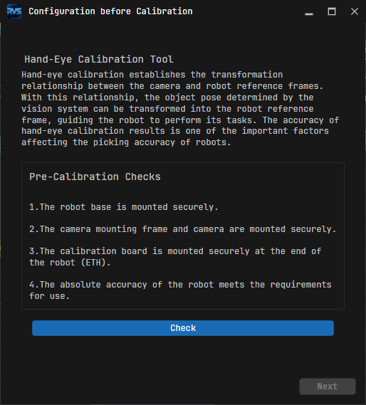
The “New calibration” option is checked by default. Simply click the
Nextbutton.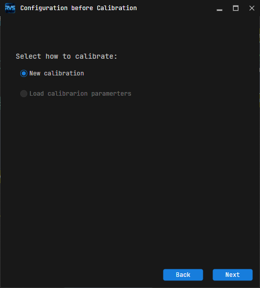
Set the Robot Euler Angle Type parameter and select the Robot Coordinate System type according to the actual robot, and then click the
Nextbutton. If you are unsure which Euler angle type your robot uses, click “Get Euler Angle Type” and follow the instructions shown in the upper-left corner of the interface.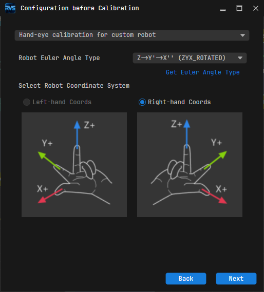
Attention
You can use the Get Euler Angle Type tool to obtain the robot’s Euler angle type. After clicking “Get Euler Angle Type”, follow the steps in the operating instructions in the upper-left corner of the interface.

In the Select a robot type for calibration window, select one of the options based on your robot type, then click the
Nextbutton.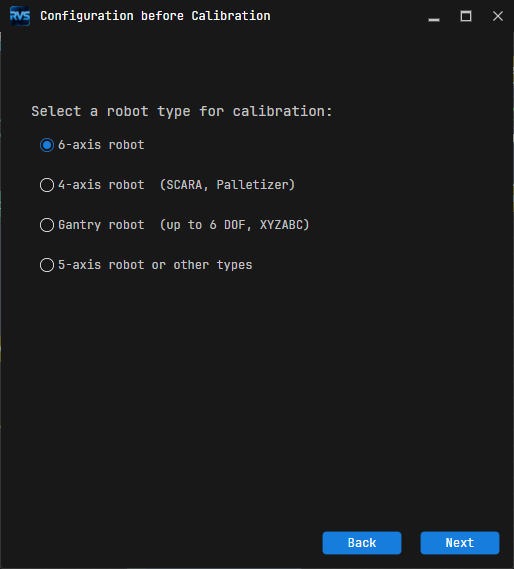
In the Select camera setup window, select the “Eye in hand” option, then click the
Nextbutton.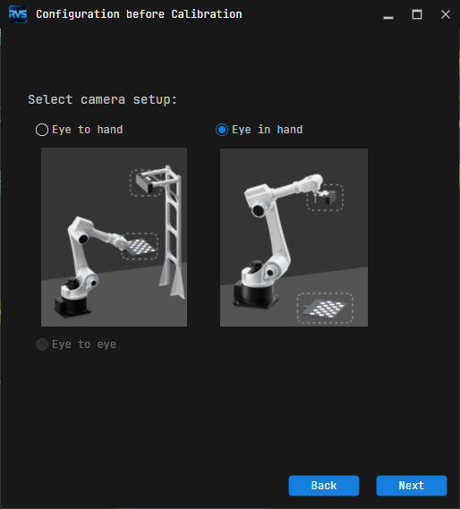
The Select how to collect data window has “Multiple random Calibration board poses” selected by default. Click the
Startbutton. The Calibration Window pops up.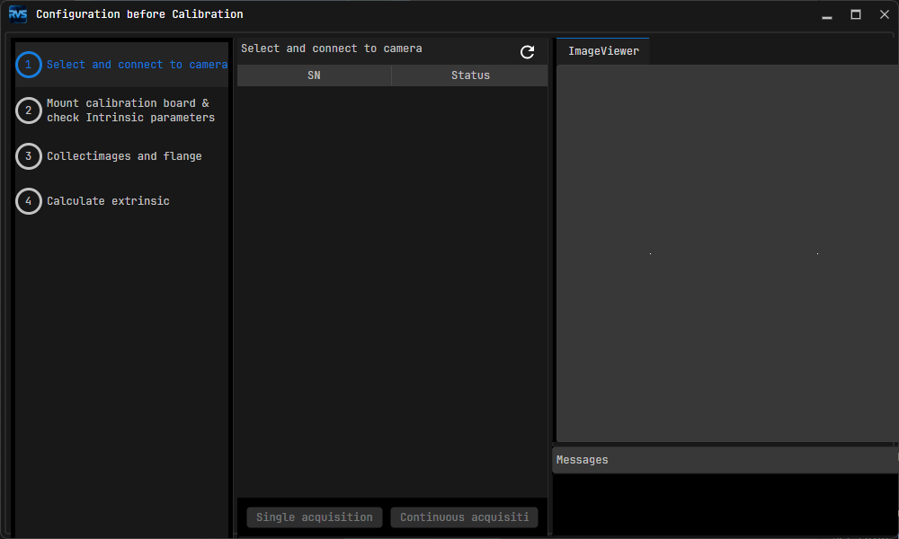
Now, the calibration presettings are complete, and the formal calibration process will begin.
Calibrate
Select and Connect to Camera
In the Select and Connect to Camera step, click
 to refresh the camera list. The camera you need to connect to should now appear in the SN list.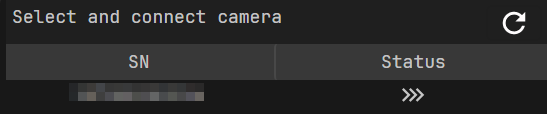
Attention
If the target camera SN does not appear in the list, check its hardware wiring and IP settings.
Click the
 button to connect to the camera.
After the camera is connected, click
Continuous AcquisitionorSingle Acquisitionto verify that the camera can capture images properly. The acquired images are displayed in the ImageViewer panel on the right.
Click the
Nextbutton:If you clicked
Single Acquisitionin step 3, click theNextbutton on the bottom bar directly.If you clicked
Continuous Acquisitionin step 3, clickStop Acquisitionfirst to stop capturing, and then clickNext. Otherwise, the camera will keep capturing continuously and affect subsequent steps.
Mount Calibration Board and Check Intrinsic Parameters
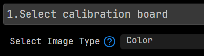
In the 1. Select Calibration Board area, first select the image type, and then select the calibration board type.
Attention
Select the image type based on the camera’s image types (e.g., whether it supports color or IR images) and hand-eye calibration requirements:
If the image type is “Color” or “Color; Depth”, you can select “Checkerboard Calibration Board” or “Standard Circular Calibration Board”.
If the image type is “IR; Depth”, you can select only “Standard Circular Calibration Board”.
Configure the calibration board parameters based on the selected board type:
For “Checkerboard Calibration Board”, enter the number of corner points in the horizontal direction, the number of corner points in the vertical direction, and the square size.

For “Standard Circular Calibration Board”, select the calibration board model.

Manually move the robot until the calibration board is clearly and fully visible in the image view on the right.
Click the
Check Intrinsic Parametersbutton in the 2. Check Camera Intrinsic Parameters area. The intrinsic parameters will appear in the Message box on the lower right.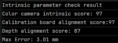
Check Success: Click the
OKbutton in the pop-up window, then click theNextbutton on the bottom bar.Check Failure: First check whether all options and parameters in the Calibration Presettings and Mount Calibration Board and Check Intrinsic Parameters processes are set correctly. If the check still fails despite confirming the settings are correct, click the
Open Percipio Viewerbutton in the Exception area to open the camera viewing tool and adjust camera parameters until the image quality meets the requirements.

Capture Images and Poses
In the Capture Images and Poses step, control the robot to move to different calibration points, then click the
Add an image and record flange posebutton.
Attention
After moving the robot to different calibration points, please record the pose of each point in the robot program so that they can be directly called during recalibration.
Enter the robot flange pose in the pop-up window.
You can enter poses in any of the following ways:
Direct modification in the pose panel: Directly adjust the coordinates (X, Y, Z) and rotation parameters.
Adjust pose offset using the pose transformation tool: Click the
Pose Toolbutton to open the Transform Pose tool. Adjust the pose by modifying the offset relative to the current position and orientation.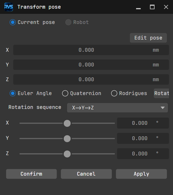
Enter via the pose editing interface: Click the
Edit Posebutton and directly enter the position and rotation information in the format indicated in the pop-up window. After clickingOK, the entered value will be synchronized to the pose panel.
Attention
It is recommended to store the robot flange poses for each calibration point in a local file (.txt or .xlsx) so they can be reused during recalibration.
Repeat the above steps until the added calibration points meet the data requirements, then click the
Nextbutton on the bottom bar.
Calculate Extrinsic Parameters
In the Calculate Extrinsic Parameters step, click the Calculate extrinsic button in the 1. Calculate extrinsic and view results area.

The Message box on the lower right side of the interface will display the extrinsic parameter calculation results.
Save and Apply Calibration Results
When RMSE < 1, the calibration accuracy can generally be considered acceptable.
Click the Save button at the bottom of the Calculate Extrinsic Parameters step. The pop-up shown below indicates the extrinsic parameters have been saved successfully. The calibration results will be automatically saved to the “Calibration” directory under the project storage path.
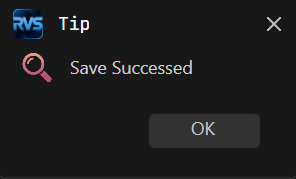
After saving the calibration parameter group, you can select the corresponding calibration parameter group in the “ImageAcquisition” step of the project in the current solution.
The calibration workflow is now complete.